Generation
In order to draw a polygon, select one of the two
Polygon tools,

or

, from the toolbox. The cursor becomes a drawing

cursor.
Use the drawing cursor to click the drawing area and, holding down the mouse button, drag the resulting circumscribed circle of the polygon across the screen. Release the mouse button when the resulting polygon is as you want it.
A polygon behaves like an ellipse while being drawn. For this reason, the same rules for drawing ellipses also apply when drawing polygons.
To set the number of corner points or sides, select the
Selection
tool. A dialog box appears for you to enter the required number of sides.
Grid Alignment
The orientation of the polygon depends on whether or not the
Grid Alignment is active when the polygon is generated. If the
Grid Alignment function is active

, the polygon is forced into one of the three major planes of the current grid depending on the direction it is dragged in.
Without
Grid Alignment
, the polygon can be turned freely.
This setting can be temporarily reversed by holding down the ALT key while dragging.
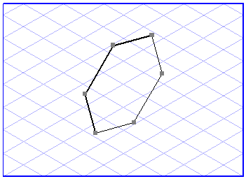
The orientation and shape of a polygon depend on the direction you drag the polygon in from the start point. Different polygons are generated depending on the direction in which you drag them.
| Should you have difficulties in determining the orientation of a polygon, try the following technique. Click the drawing area with the Polygon tool and, holding down the mouse button, move the cursor in a circular pattern. You will see how the orientation and the shape of the displayed circumscribed circle change. |
Grid Snap and Element Snap
You generate a polygon by dragging it either from the center point or from a vertex, depending on the tool you choose. The start and end points can be attracted by neighboring grid or element points. Whether or not they are attracted depends on the current setting of
Grid Snap
and
Element Snap
.
The Grid Snap setting can be temporarily reversed by holding down the CTRL key while dragging.
Show Dimensions on the Element
If the
Show dimensions
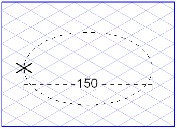
option has been activated, the diameter of the circumscribed circle is displayed while the polygon is dragged.
Displaying Dimensions in the Dimensions Bar
When the polygon is dragged, the dimensions bar shows three dimensions relating to the circumscribed circle. The dimensions indicate the diameter, ellipse value and orientation angle of an ellipse (in this order).
When you release the mouse button, the display fields show a maximum of three dimensions for the last polygon segment drawn. These dimensions indicate the length, true length and orientation angle of a line (in this order).
If the polygon has been selected, you can change every dimension directly in these fields. The fact that changes to dimensions only affect the last segment should be borne in mind when making changes. Confirm your entry with the ENTER key. If you do not confirm your entry, Arbortext IsoDraw will confirm it automatically after a few seconds. Use the TAB key to move from one field to another.
Use the Element info dialog box to change the dimensions of the other polygon segments.