Generation
To draw a line, select the
Line
tool from the toolbox; the cursor becomes a drawing

cursor.
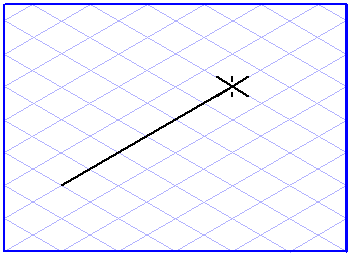
Click the drawing area and, while holding down the mouse button, drag the resulting line to the required end point. The line is generated as soon as you release the mouse button.
In order to draw a polyline, select the
Drawing of polylines
tool from the toolbox. Use the drawing
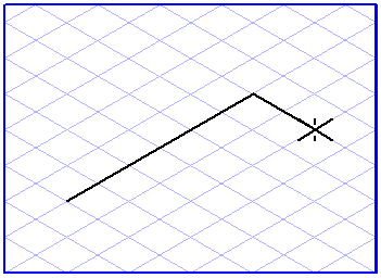
cursor to click the drawing area and, holding down the mouse button, drag the resulting line to the required end point of the first segment. Now release the mouse button. Now click the drawing area. You will see that the end point of the first segment changes into the start point of the next segment. Drag the line across the screen and then release the mouse button. You can also add on further segments, if required.
You can terminate the generation of a polyline automatically by linking the last segment generated to the start point. This will leave you with a closed polyline. To terminate creation of an open polyline, click the toolbox.
You can also terminate the drawing process by pressing the CTRL key which activates the arrow cursor, and then by clicking the drawing area.
Grid Alignment
The orientation of the lines depends on whether or not the
Grid Alignment function is active when the lines are generated. If the
Grid Alignment function is active

, lines can only be drawn in the direction of the major axes of the current grid or in the horizontal plane.
Without
Grid Alignment
it is possible to draw lines in any orientation. This setting can be temporarily reversed by holding down the ALT key while dragging the line.
Grid Snap and Element Snap
The start and end points of lines and segments of a polyline can be attracted by neighboring grid or element points. Whether or not they are attracted depends on the current setting for
Grid Snap
and
Element Snap
.
The Grid Snap setting can be temporarily reversed by holding down the CTRL key while dragging.
Show Dimensions on the Element
If the
Show dimensions
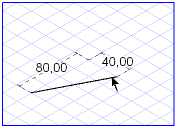
option has been activated, length information is displayed for the relevant line segment while the line is being dragged. If the line is located on one of the major axes of the current grid or in the horizontal plane, the length of the line will be displayed. If this is not the case, two dimensions will be displayed – namely, the lengths along the two major axes involved.
Displaying Dimensions in the Dimensions Bar
The dimensions bar shows a maximum of three dimensions when a line is dragged. The first field shows the length of the line without perspective foreshortening. The second field shows the actual length of the line, i.e. the true length. The third field indicates the orientation angle of the line relative to the horizontal.
If a line has been selected, you can change every dimension directly in these fields. Confirm your entry with the ENTER key. If you do not confirm your entry, Arbortext IsoView will confirm it automatically after a few seconds. Use the TAB key to move from one field to another.
In the case of a polyline, the bar will show the dimensions of the last segment drawn. Use > to obtain the dimensions of the other segments.