Explosion Tool
The
Explode assemblies
tool gives you the means to automatically explode the components of a larger assembly unit along a specific axis. Individual parts are spatially separated. Explosion always goes as far as necessary till the parts no longer overlap. If all the components of an assembly unit lie on a single axis (e.g. a shaft with bearing, flange and fastening units), you can select the tool for the entire drawing directly. In the case of assembly units where components are added in a different direction to the major axis (e.g. gear housing with angled threaded plug), you must first select all components in one direction (axis).
If components (e.g. a threaded plug) lie outside the major axes, you can create a suitable axis before exploding using the 3D axis selector. Provided no coordinate system axis is selected afterwards, the selected parts will be exploded on the free axis.
You have used the
Objects window or the
Arrow
tool to select all assemblies on a given axis and/or all assemblies (drawing with one axis). Click the
Explode assemblies tool.
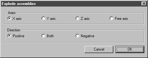
The following dialog box appears:
Axes
Here you can select the axis along which you wish to explode the assemblies. The choice of axis must therefore agree with the axis in the drawing on which the components are located. If there is no free axis, the Free axis option remains grayed out and without function.
Direction
You can use this setting to specify the direction on the free axis that is to be used to pull the assemblies apart. If you select individual assemblies, you can explode them straightaway in the direction in which they were assembled.
If you select Positive, the assemblies will be exploded in the direction with axis designation (X, Y, Z). If Negative is set, they will be exploded in the opposite direction. If you select Both, the parts will be pulled apart in both axial directions. The direction in this case depends on the extent and the orientation of the assemblies.
If the explosion tool is used on a free axis, the arrow on the blue axis defines the positive direction.
You can also move each assembly along the axis subsequently.
Once you have completed your settings, click OK. The selected assemblies are then exploded in accordance with this setting. Clicking Cancel closes the dialog box without changing the orientation of the assemblies.
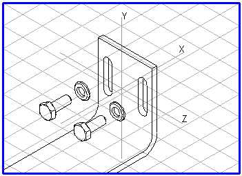
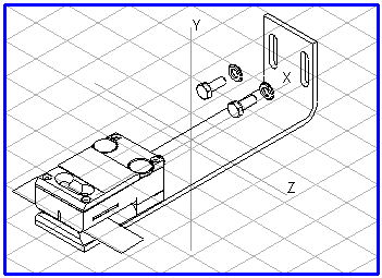
In the example, the X axis and direction Negative have been selected.
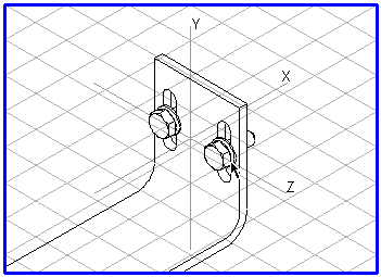
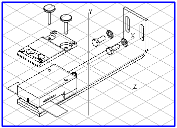
The following examples show the sequence of operations:
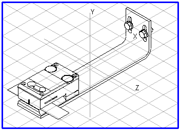
The Bracket assembly unit in assembled form, the bracket with fastenings exploded in the X axis’ negative direction, and the bracket with fastenings and cover exploded in the Y axis’ positive direction.