Ellipse
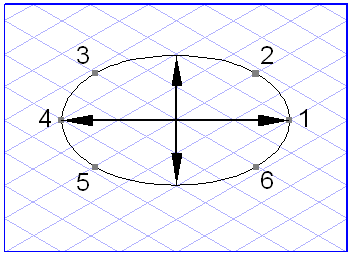
An ellipse consists of six points, the arc segments and the center point.
Points 1 and 4 represent the vertices of the ellipse. The distance between them is the diameter. The minor axis runs through the center point at right angles to the diameter. Points 2, 3, 5 and 6 mark the intersection points between the ellipse and the major axes of the perspective plane on which the ellipse is located.
In a perspective illustration, the ellipse represents the projection of a circle onto an imaging plane (drawing plane). Its appearance is determined by the ellipse value and the orientation angle. These two values define the perspective plane of the ellipse.
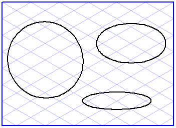
The ellipse value indicates the degree to which the original circle is tilted with respect to the imaging plane. A circle in a technical drawing has an ellipse value of 90°. If the circle is tilted backwards, the ellipse value reduces: The form changes into that of an ellipse. The ellipse value can be reduced down to 0°: All that remains is a line.
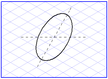
The ellipse now has to be rotated so that it lies on the correct axis. This is controlled by the orientation angle. The orientation angle indicates the inclination of the ellipse diameter relative to the horizontal axis. An angle of 0° or 180° means that the ellipse is horizontal. This is so if it is lying on the flat top surface of a cube, for example.
| Circles always have an orientation angle of 0°. |