Dimension, Linear
You can use this tool to add a dimension to the distance between two freely selectable points. In the simplest case, a dimension can be generated between the start and end points of a line. Because you can freely select the starting points for the dimension, you can define any dimension on the line connecting the start and end points of an element. A dimension that includes multiple elements can also be generated.
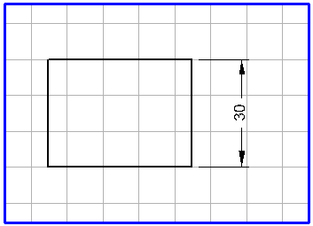
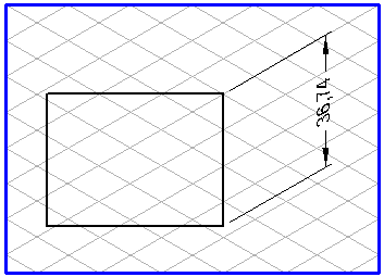
The alignment of the leader lines depends on the grid currently set. These leader lines are always dragged parallel to the major axes. The text element is also oriented in accordance with the current grid. The two examples that follow show the difference in the alignment in relation to the grid used.
Select the
Dimension, horizontal
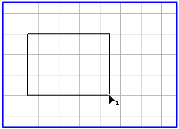
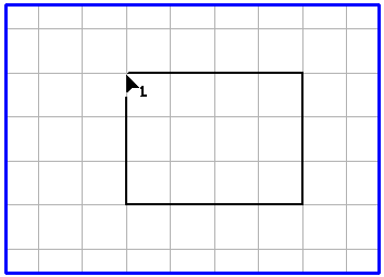
tool from the toolbox. The cursor becomes an arrow tip 1

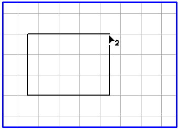
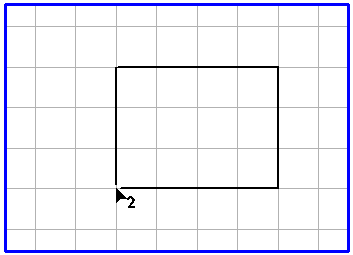
cursor. This means that you should now select the position for the start point of the dimension. Click on the required point on the element. When you have hit the element, the cursor becomes an arrow tip 2

cursor, thereby requesting you to select the position for the end point of the dimension. Select the point by clicking it and holding down the mouse button.
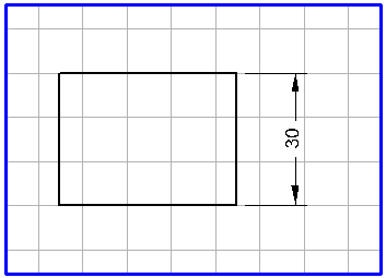
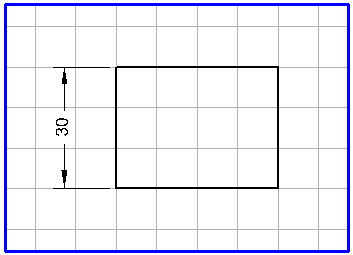
The example shows the steps involved in defining a dimension:
Now, when you move the mouse, you can see the leader lines, the dimension arrows and the dimension itself. Drag the leader lines until they are at the required distance from the elements of the drawing.
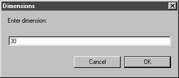
When you release the mouse button, the following dialog box will appear:
The dimension, as determined by Arbortext IsoDraw, is shown in the entry field. Clicking on OK confirms the preference. If you want to enter another dimension or some text, click in the entry field and enter your data. Then confirm with OK. If you click on Cancel, the dimension generation process will be aborted.
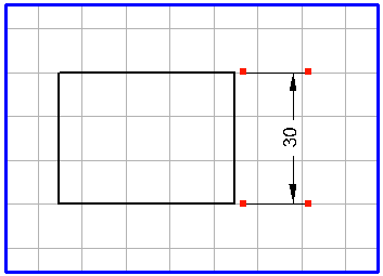
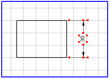
When you exit the dialog box with OK, the dimension appears on the drawing. All the elements associated with the dimension (leader lines, dimension arrows and the text element) are grouped. If you want to edit individual elements later, you must first ungroup the elements using > .
The direction in which the leader lines are dragged depends on the order in which you select the two dimension points.
When you select the dimension points with the arrow tip (1)
cursor, then the arrow tip (2)
cursor—from left to right/from bottom to top—the leader lines are dragged downwards/to the right. When selecting from right to left/top to bottom, the leader lines point upwards/to the left.
If you hold down the SHIFT key while dragging the leader lines, their direction is reversed.
If a dimension is to relate to element points, the cursor must contact the element points. Element points have a magnetic effect thanks to the magnetic radius. The element points are always contacted when you click inside the magnetic radius. The magnetic radius is set on the
Grid preferences panel under > . (See
Preferences.)
The appearance of the leader lines, dimension arrows and dimension (text element) depends on the preferences that have been set. With the menu command > , you can set the pen attributes and the different distances for the leader lines and dimension arrows on the Dimensions preferences panel. You can select the font, set the number of decimal places and define the vertical distance to the dimension arrows. This vertical distance determines whether one or two dimension arrows are generated.