Dimension, Diameter
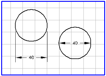
You can use this tool to add dimensions to a circle, ellipse or any segment of these elements with a diameter.
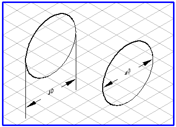
The generated dimension can lie inside the element with the dimension arrows or outside the element with additional leader lines as with the Dimension, horizontal tool. The leader lines are dragged parallel to the grid axes. When the dimension arrows/leader lines appear, they are located in one of the three major axes of the grid. With a movement of the mouse, they jump to the next axis. The orientation of the text is shown in accordance with the orientation of the circle/ellipse which dimensions are being added to.
If you hold down the ALT key when the dimension arrows/leader lines appear, the dimension arrow can be freely rotated within the contour of the element. The leader lines outside the element can also be freely rotated around the contour. The orientation of the displayed dimension changes with the orientation of the dimension arrows/leader lines. You can use this function for optimum alignment of the dimension position relative to the reference element.
Select the
Dimension, diameter
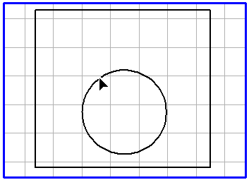
tool from the toolbox. Click on any point on the element that you want to add a dimension to. Hold down the mouse button.
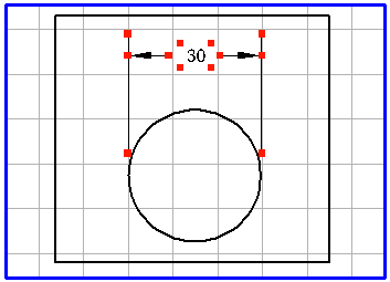
In this example, a dimension is added to a bore:
Move the mouse. When the cursor is inside the element, you will see the dimension arrows along with the dimension. When you move the cursor outside the element, the leader lines also appear. Move the cursor to the position where the chosen dimension is required and find the optimum dimension position by freely rotating the dimension.
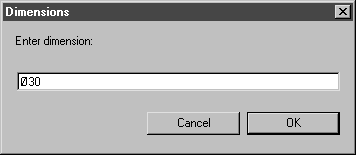
When you release the mouse button, the following dialog box will appear:
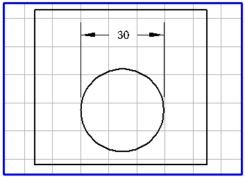
The dimension, as determined by Arbortext IsoDraw, is shown in the entry field. Clicking on OK confirms the preference. If you want to enter another dimension or some text, click in the entry field and enter your data. Then confirm with OK. If you click on Cancel, dimension generation will be aborted.
When you exit the dialog box with OK, the dimension appears on the drawing. The elements relating to the dimension (leader lines, dimension arrows and the text element) are grouped. If you want to edit individual elements later, you must first ungroup the elements using menu command > .
The appearance of the leader lines, the dimension arrows and the dimension (text element) depends on the preferences set previously. With menu command > , you can set the pen attributes and the different distances for the leader lines and dimension arrows in the Dimensions preferences panel. You can select the font, set the number of decimal places and define the vertical distance to the dimension arrows. This vertical distance determines whether one or two dimension arrows are generated.