Dimension, Angle
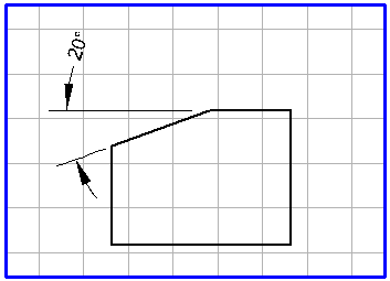
This tool can be used to add dimensions to the angle between two elements. On a technical drawing, it is often necessary to add dimensions to a chamfer on the work piece. In this case, you must draw a leader line as a second element before adding dimensions.
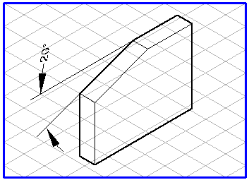
The generated dimension arrows depend on the grid which is currently set. In one view, the dimension arrows are generated from a circle. If there is a perspective grid in the background, the dimension arrows are created from the ellipse in one of the three major planes. Moving the mouse makes the auxiliary ellipse jump to the next major plane. The orientation of the text is adapted to match the orientation of the ellipse.
If you hold down the ALT key when the auxiliary ellipse appears, the latter can be freely rotated, as with an Ellipse element. The orientation of the displayed dimension changes with the orientation of the ellipse. You can use this function for optimum alignment of the dimension arrows relative to the reference elements when adding dimensions to a perspective drawing.
Select the
Dimension, angle
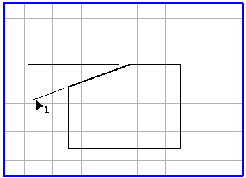
tool from the toolbox. The cursor changes to an arrow tip (1)

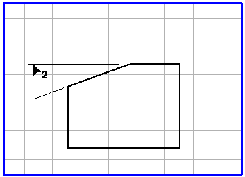
cursor. This indicates that you should now select the first element of the angle. Click on the first element for the angle. When you have hit the element, the cursor changes to an arrow tip (2)

cursor, thereby requesting you to select the second angle element. Select the element by clicking it and hold down the mouse button.
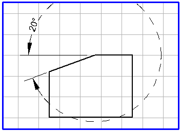
The example shows the steps involved in defining an angle dimension. The leader lines have already been drawn:
When you move the mouse, you will see the outline of an auxiliary circle with the dimension arrows and the angle dimension. Drag the circle to the required orientation for the dimension arrows.
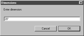
When you release the mouse button, the following dialog box will appear:
The dimension, as determined by Arbortext IsoDraw, is shown in the entry field. Clicking on OK confirms the preference. If you want to enter another dimension or some text, click in the entry field and enter your data. Then confirm with OK. If you click on Cancel, generation of the angle dimension will be aborted. This vertical distance determines whether one or two dimension arrows are generated.
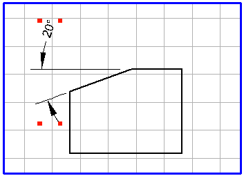
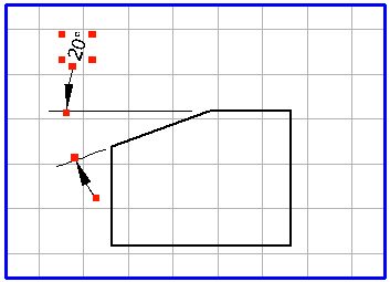
When you exit the dialog box with OK, the angle dimension appears on the drawing. All the elements associated with the dimension (dimension arrows and the text element) are grouped. If you want to edit individual elements later, you must first ungroup the elements using > .
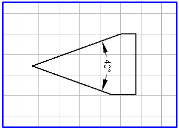
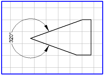
The angle dimension between the elements clicked on in succession (sides of the angle) is always generated. When the circle or ellipse appears with the dimension arrows after clicking on the elements and you hold down the SHIFT key, the explementary angle is generated.
without SHIFT key | with SHIFT key |
| |
The appearance of the dimension arrows and the dimension (text element) depends on the preferences that have been set previously. With the menu command > , you can set the pen attributes for the dimension arrows on the Dimensions preferences panel. You can select the font, set the number of decimal places and define the vertical distance to the dimension arrows.