Program Preferences Example
Program preferences are to be set up for creating spare parts drawings with callouts in an isometric representation.
All the parts are to be depicted in scale with one another. A relatively large number of parts of small extent will be used. The completed drawings are to be used for both a printed version and an online version.
Following are steps to create these preferences:
1. Arbortext IsoDraw is open, but no windows are open.
Select the > menu.
|
|
Clicking on the symbols to the left opens the corresponding preferences panel.
|
The standard settings on the Grid preferences panel are adopted.
2. Select the Drawing preferences panel.
3. Enter A4 next to Format and select Landscape next to Orientation. Confirm by clicking OK.
4. Select the Threads preferences panel.
|
|
There will be several parts with small thread diameters and lengths in the drawings that are to be produced. The distance between thread turns should therefore be adjusted so that the thread turns remain visible.
|
5. For the inner and outer threads, enter 12 next to the first up to and 1.5 for the relevant Distance. Enter 25 next to the second up to and 2.0 for the relevant Distance. For over, enter 2.4 next to Distance. Confirm by clicking OK.
6. Select the Attributes preferences panel.
|
|
As the parts are to be drawn in detail and small parts are to be depicted, the thicknesses of the standard pens must be changed accordingly. A new pen must also be set up for the callout reference lines. The callout style Normal must also be adjusted.
|
7. Click on the Pens button.
The Edit pen dialog box appears with the Thick pen.
8. Enter 0.22 next to Width.
9. Then click on the forwards arrow button and enter 0.16 next to Width for the Medium pen. Change the width of the Thin and Center line pens to 0.1.
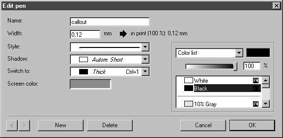
10. Click on the New button to specify a pen for the callout reference lines.
11. Enter callout next to Name and set up the pen according to the information in the figure.
12. Then click OK.
You will return to the Attributes preferences panel.
13. Click on the Callouts button.
14. Click the Line button in the Edit callout style dialog box.
15. Select the callout pen that you have just set up from the Line options dialog box. Confirm your settings here and in the Edit callout style dialog box by clicking OK. Click OK to confirm your entries on the preferences panel.
16. Select the misc preferences panel.
| This page enables you to set various features such as automatic save. Selecting automatic save means that there is no need to manually save the file at various points while working on it. Also, by saving your work at regular intervals, it prevents the loss of large amounts of work should a problem occur with your software or hardware. |
17. Click on the box next to use under the Automatic Save option and enter 5 next to Period. Confirm by clicking OK.
The program preferences are now set according to the specifications of the example drawings and are saved by exiting the program.