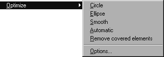
Optimize
The problem which often occurs when importing CAD data is the poorly suited structure of the drawing for the illustration. Polylines are often used to represent circles, ellipses or curves. Polylines are adjoining line segments which are intended to approximate a curve. They are imported as polylines if they consist solely of straight segments. Otherwise, they are converted into Bézier paths. Elements of this type are naturally much more complex to edit than, for example, ellipses drawn in Arbortext IsoDraw . An additional disadvantage is the large volume of data involved.
For cases of this type, Arbortext IsoDraw offers five optimization functions which attempt to generate better elements from polylines.
The Remove covered elements command will help you reduce the size of the file.
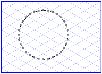
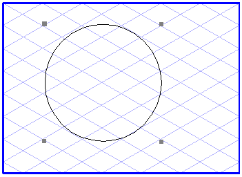
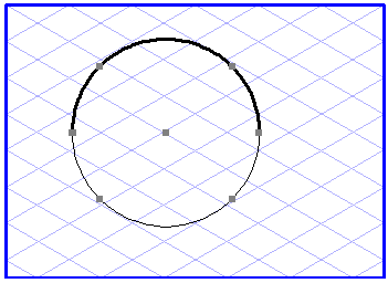
Circle
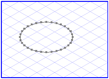
Select a polyline or a Bézier path which looks like a circle or part of a circle, then choose > > . Arbortext IsoDraw now calculates whether all element points of the selected element lie close enough to an arc. If this is the case, the circle is generated. Several polylines or Bézier paths can also be optimized simultaneously. After optimization has been performed, the old elements lie grouped in front of the circles. Check that the contours of the new circles lie precisely enough on the old elements. Delete the group if they do. Only the circles then remain on the illustration.
Ellipse
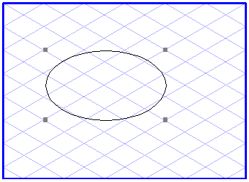
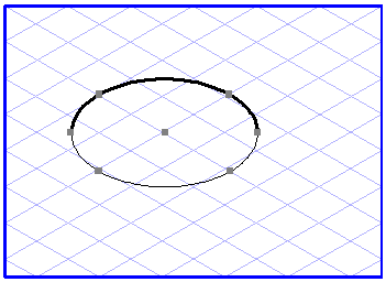
The Ellipse variant functions in a similar way to the circle optimization. In this case, of course, ellipse-shaped polylines or Bézier paths need to be selected before you call up the command.
| Optimization to an ellipse can only be performed if the selected polylines or Bézier paths are closed. |
Smooth
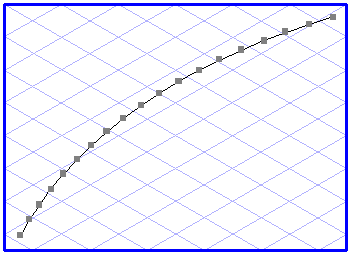
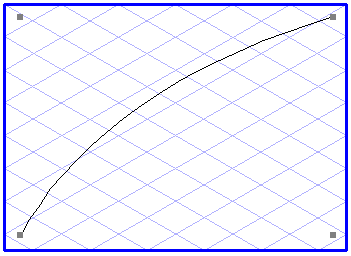
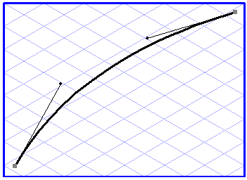
The smoothing function is applied to polylines or Bézier paths which cannot be converted to circles or ellipses. First select the polylines or Bézier paths, then choose > > . For each selected element, Arbortext IsoDraw now calculates a curve which approximates the element as smoothly as possible and uses the fewest number of points. Here, too, the old elements are grouped together in front of the newly generated Bézier curves.
Options (for Smoothing)
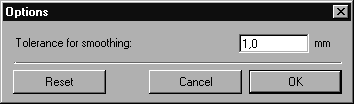
Use the Options command in the submenu to specify how strongly the elements are to be smoothed. The default tolerance is 0.1 mm. If you select a larger value, the smoothing function is more vigorous. With a smaller value, a smoothing function takes place which is more precise and in line with the contour flow. The tolerance value specifies how far the smoothed curve may be from the original polyline.
Enter the required value. If you click Reset, the default value is restored.
The Cancel button allows you to exit the command without making any changes. If you confirm your entry with OK, the value will be used for the smoothing function.
| The smoothing function employs an approximation procedure for the calculation. The result may therefore not agree with your expectations, especially for rough smoothness tolerance values. Sharp corners in the curve profile may be quite desirable, they may nevertheless be smoothed out. Remember: The lower the value you select for the tolerance, the more elements the drawing will contain. Typical values lie in the range 0.5 mm to 0.01 mm / 0.02 to 0.001 inches. |
Automatic
The fourth function in the Optimize submenu attempts to generate enhanced results from selected polylines or Bézier paths by repeated optimization. The following successive steps are performed:
Firstly, successive checks are made to determine whether circles, parts of circles or ellipses can be generated from the selected elements. The remaining polylines are then smoothed.
Delete Covered Elements
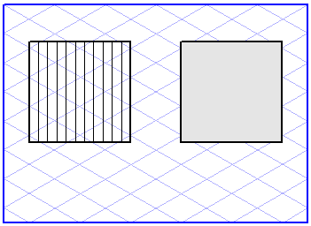
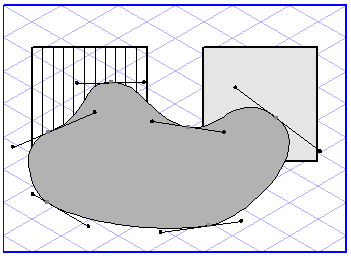
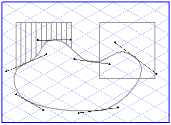
The last function in the Optimize submenu deletes elements which are covered by filled areas and are therefore hidden. This is the case, for example, if you use white areas to cover specific parts of an illustration.
Select the filled elements hiding the elements you want to delete. Select all the elements if you want to optimize the entire illustration. If you now apply the Remove covered elements command, all the elements are checked to determine whether they are covered in full or in part by one of the selected areas. If this is the case, the element will be deleted either entirely or in part.
This is not the case with elements which have been locked or are located on locked layers. The procedure is different for elements which themselves are filled. These are only deleted if they are covered completely (see graphic at bottom right of preceding page).
| Before applying the function, you should save the file under a new name, since Arbortext IsoDraw will be unable to reconstruct the deleted areas of your illustration afterwards. |