The Major Isometric Axes
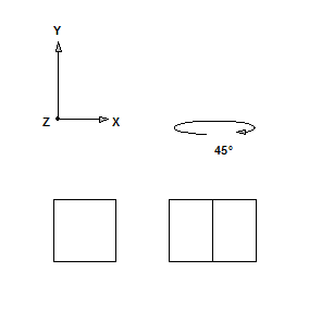
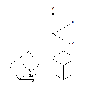
Starting from the normal front view, the isometric orientation of a technical drawing is rotated through 45° around the Y axis. The body is then tipped forward, towards the observer. When a tipping angle of 35°16’ is reached, sections that are of equal length are also depicted with equal length in the various major axes. By way of example you can see a cube rotated in isometric representation.
The figure on the left depicts the front view and the cube after having been rotated through 45°. The figure on the right depicts the side view of the cube after it has been tipped. The cube next to it is depicted in the major isometric axes.
The major axes of the isometric coordinate system have fixed angles in the drawing. The Y axis remains vertical, as in the Cartesian coordinate system. However, the X axis and the Z axis are tilted by 30° and -30° respectively, relevant to the horizontal. Therefore, the angle between the major axes in an isometric representation is 120°.
These axes form the basis for all isometric drawings. As a result, a sheet with a grid is often laid under the drawing sheet during manual drawing work to make it easier to draw on the axes.
Major Isometric Axes
When Arbortext IsoDraw is launched, an isometric grid is displayed on the drawing area. Two functions that help when drawing with the grid are set by default – align to grid and snap to grid points. The first exercise will cover these functions in greater detail.