Inserting the Screws into the Practice Drawing
1. In the file screw.idr, select all the elements of the drawing and group them using the > menu.
2. Duplicate the group and cut the duplicate.
|
|
The Duplicate, Cut, and Paste commands can be found in the Edit menu. Note that when you duplicate the group, the duplicate is directly on top of the original so you won't see a second copy of the group.
|
3. Return to the transform.idr window.
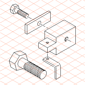
4. Select the Paste command. The screw appears on the drawing area.
|
|
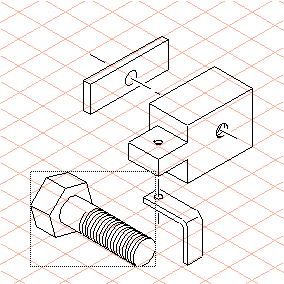
You will notice that the threads of the screw have a much larger diameter than the two threaded bores.
|
Select the threaded bore at (1).
Its diameter measures 15 mm, or 50% of the screw thread’s diameter.
| If you want to check the thread diameter of the screw, select the screw then go to the > menu. Select the thread ellipse. The diameter is indicated in the dimensions bar. |
5. Select the screw.
6. Select the
Scaling
tool from the toolbox.
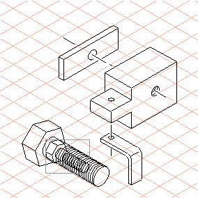
A dotted rectangle appears around the screw.
The cursor changes into the center

cursor.
7. Hold down the SHIFT key and click in the area around the screw.
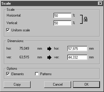
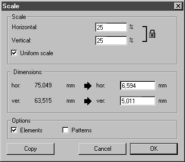
The Scale dialog box appears.
8. Enter 50 next to horizontal and confirm by clicking Copy.
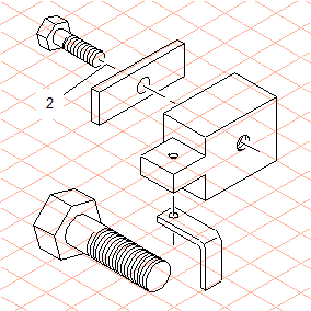
A scaled copy of the screw appears.
9. Move this copy so that the center of the thread ellipse is in line with the end dot of the center line (2).
| The screw is now positioned over one part of the center line. In order that the halo of the center line remains visible, it must be aligned on top. |
Select the center line and go to the > menu.
10. To adjust the angle required for the second screw location, reselect the original (larger) screw.
11. Select the
Rotation
tool.
The cursor changes into the center
cursor.
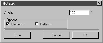
12. Hold down the SHIFT key and click in the area around the screw. The Rotate dialog box appears.
13. Enter 120 next to angle and confirm by clicking OK.
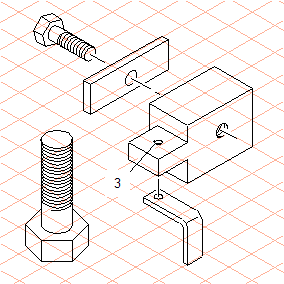
The screw rotates around 120°.
| The screw is now in the correct orientation, but is not yet the correct size. It still needs to be scaled. |
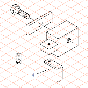
14. Select the threaded bore at (3).
Its diameter measures 7.5 mm, or 25% of the screw thread’s diameter.
15. Select the screw.
16. Select the
Scaling tool from the toolbox.
A dotted rectangle appears around the screw.
The cursor changes into the center
cursor.
17. Hold down the SHIFT key and click in the area around the screw. The Scale dialog box appears.
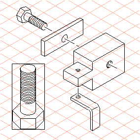
18. Enter 25 next to horizontal and confirm by clicking OK.
The scaled screw appears.
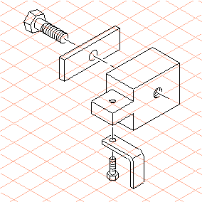
19. Move the screw so that the center of the thread ellipse is in line with the end dot of the center line (4).
| The screw is now positioned over one part of the center line. In order that the halo of the center line remains visible, it must be aligned on top. |
Select the center line and go to the > > menu.
Both screw connections are now complete.