Draw a Screw
1. Select the > menu.
2. Select the
Outer thread
tool from the toolbox .
The cursor changes into a drawing

cursor.
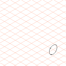
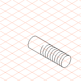
3. Starting from a grid cross, drag an outer thread ellipse (drag from the center point up and to the right).
| The ellipse that has been drawn has a green-edged thread point at the top. |
The ellipse is still selected.
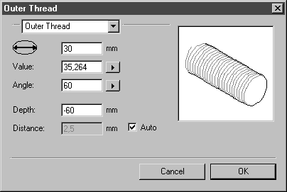
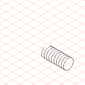
4. Select > menu.
5. Enter values for the diameter (30) and the (thread) Depth (-60) in the dialog box and click OK.
6. Select the
Ellipse
tool from the toolbox.
The cursor changes into a drawing
cursor.
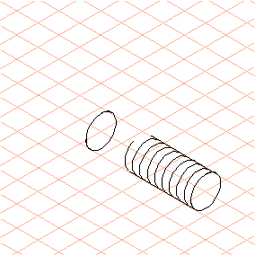
7. Making sure to leave sufficient distance from the end of the thread, drag an ellipse on the same grid line (drag from the center point down and to the left).
8. Enter 30 in the first panel of the dimensions bar to set a diameter of 30 mm for the ellipse.
9. Select the
Line
tool from the toolbox.
The cursor changes into a drawing
cursor.
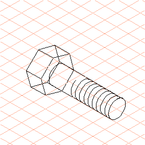
10. Drag a connecting line from each outer point of the ellipse to the outer edge of the thread.
Select the
Arrow
tool.
Select the lower half of the ellipse.
Press the F6 key (the command code for the > > command).
The lower half of the ellipse is automatically deleted.
11. Select the
Polygon
tool from the toolbox.
The cursor changes into a drawing
cursor.
12. Place the cursor on the center point of the remaining ellipse section and drag a polygon with a diameter approximately double the size of the thread’s diameter (drag from the center point down and to the left).
13. Select the
Arrow tool and then briefly press the CAPS LOCK key.
The cursor changes into a double arrow

cursor.
14. Referring to the Dimensions display, hold down the SHIFT key and drag the polygon by approximately 25 mm.
Press CAPS LOCK again.
The normal arrow cursor returns.
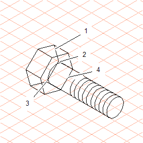
15. Click on the lower half (1) of the second polygon you created.
Press the F5 key (the command code for the > > command).
Click on both of the exterior green-edged points. The section of the polygon between these two points is then deleted.
Select both connecting lines (2, 3) and delete these using the DELETE key.
Select the lower line (4) of the first polygon. To do this, hold down the ALT key and click on the line. Press the DELETE key.
The line is removed.
Click on the lower half of the ellipse and press the F6 key. This section of the ellipse is automatically deleted.
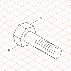
16. Change the outer edges of the screw head from the thin pen to the thick pen by double clicking on each outer edge.
The drawing of the screw is complete.
17. Save the screw you have drawn with the filename screw.idr.
The drawing will be used again in the next exercise.