Exercise 2: Create a Profile Body and Change the Orientation in 3D Mode
1. Select all the elements of the second view.
2. Choose > > .
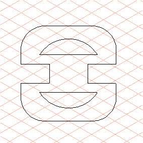
3. The profile body appears on the drawing sheet in the same way as it did in the first exercise.
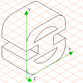
4. Select the > menu.
Arbortext IsoDraw changes to 3D mode.
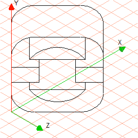
The profile body is now located on the 3 axes of the coordinate system.
5. Select the
Rotation
tool from the toolbox.
The cursor changes into the center

cursor.
6. Click on the Y axis.
The Y axis is now highlighted in red.
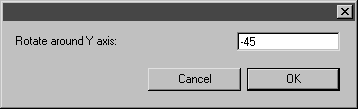
7. Now hold down the SHIFT key and click in the area around the Y axis.
The following dialog box appears.
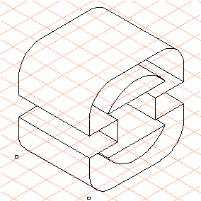
8. Enter -45 and confirm by clicking OK.
The profile now appears rotated clockwise through 45° around the Y axis.
9. Select the
Rotation tool from the toolbox again.
The cursor changes into the center
cursor.
10. Click on the X axis.
The X axis is now highlighted in red.
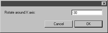
11. Now hold down the SHIFT key and click in the area around the X axis.
The following dialog box appears.
12. Enter -30 and confirm by clicking OK.
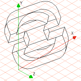
The profile now appears rotated accordingly around the X axis.
As you can see, any perspective orientation can be set for the profile.
| You can also use the > menu to choose between certain specified projection types. You can use the other tools and commands available in 3D mode to change the profile body as well. To find out more, read the 3D transformations section in the Arbortext IsoDraw User's Reference. |
No further changes are to be made to the profile in this exercise.
13. Click the
Convert to 2D illustration
button in the toolbar to quit 3D mode.
The changed profile body reappears in the normal Arbortext IsoDraw window in the Extrusion tool editing mode.
14. As in the first exercise, use the Translation Surface dialog box to set the profile length to 25 mm and select the closed cuts function.
15. As in the first exercise, exit the projection using the Projection dialog box.
16. The elements are projected. The profile drawing is finished.