Using Lattices in Creo Simulate
About Lattices
A lattice is a framework structure created in Creo Parametric that is used to reduce the amount of material used in 3D printing, thus optimizing the weight of the part that you create.
You can run structural and thermal analyses on the 3D printing lattices created in Creo Parametric to ensure that the model retains its structural and thermal integrity with a lattice structure defined. You can also run optimization studies to optimize the lattice configuration. In this way before printing the part it can be analyzed for structural and thermal capability.
You can open two types of lattices created in Creo Parametric.
• Full geometry–In this case the entire lattice geometry is transferred to Creo Simulate as a solid and takes a longer time to open.
• Simplified lattice–These lattices are specifically for use with Creo Simulate. When you open a model with a simplified lattice in Creo Simulate, the model is reconverted to a full geometry lattice. You need to note the following points:
◦ 2.5D Lattice–Gets converted into shells. You can select individual quilt surfaces in the model in Creo Simulate.
◦ 3D Lattice–Lattice arms (beams) are converted to beam idealizations in Creo Simulate. End points of the beams are converted to mass idealization if you specify the end points as balls in Creo Parametric. The beam idealizations are placed with the same orientation in the simplified lattice and the full geometry lattice.
These automatically created idealizations cannot be edited and are not available in the Model Tree. However, you can view information for these objects.
◦ When beams with variable diameter are created in a simplified lattice, they are represented by Creo Simulate beam idealizations with variable beam diameter.
◦ If a lattice beam idealization is connected to a solid element the following two cases arise:
1. Opposite beam end is free—In this case a constraint with all 3 rotational degrees of freedom is automatically created at the connection between the beam and the solid element.
2. Opposite beam end is connected—In this case the following occurs:
▪ A coordinate system CSYS is created along the beam axis.
▪ A constraint with the rotational degree of freedom fixed in the X- direction is created at the connection between the beam and the solid element, using the created CSYS.
◦ A beam release is created at beam and solid joints if the Inertia Relief check box is selected for an analysis.
◦ You can selectively apply loads and constraints to different points, surfaces and volumes within the lattice geometry in Creo Simulate and study the effects of different loads or constraints on the lattice, and on the model.
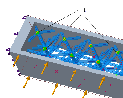
◦ When you define a load, you can select all the points that are part of a lattice and that lie on the outer boundaries of the lattice and apply loads at these points. To do this, select Points as the reference and then select Lattice Set on the load dialog box. All the points on the outer boundary of the model are selected as shown in the following figure:
1. All points on the outer boundary are selected when you select a single point.
◦ When you view the results of an analysis that contains a lattice, you can view result quantities for either an individual beam or the entire lattice.
◦ When you run an optimization study for a model with a lattice defined for it, when the study is completed, a directory with the name .optimized_model is created inside the study directory and contains the optimized model that can be opened in Creo Parametric and modified for optimized results.
Example: Optimizing a 3D Lattice using Creo Simulate
The following example demonstrates how you can use Creo Simulate to optimize a 3D lattice structure for a model.
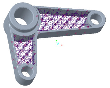
1. Convert the lattice to a simplified lattice by selecting Simplified on the Lattice tab in Creo Parametric. Alternatively select Simplified during lattice creation. The model with a simplified lattice is as shown in Fig 1.
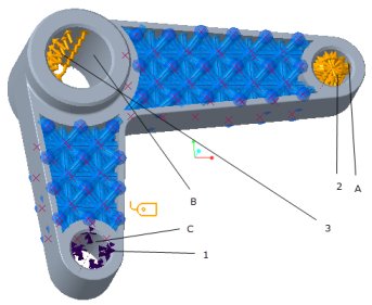
2. Open the model in Creo Simulate. The model when opened in Creo Simulate is as shown in Fig 2.
Fig. 1 Part created in Creo Parametric with simplified lattice | Part opened and regenerated in Creo Simulate Fig. 2 a. Displacement constraint- fixed for translation in X-,Y-, and Z- direction on surface C b. Bearing and pressure loads on surface A c. Bearing load on surface B d. A,B,C—Inner surfaces of holes |
3. Create a bearing load on surface B with a value of 25 N in the X- direction and 15 N in the Y- direction. Create a bearing load with a value 100 N in the Y- direction on surface A. Create a pressure load on surface A with a value of 10MPa.
4. Create displacement constraints on surface C to fix translation in the X-,Y- and Z- directions
5. Create and run a static analysis for the model to compute basic parameters for the model.
6. From the static analysis, the total mass of the model is computed as 2.873835e-03 tonne.
7. Create a global optimization study with a design goal of minimizing the total mass of the model. Set the design limits as follows:
◦ Maximum Von Mises stress must not exceed 30.00000 N/M2
◦ Maximum Displacement in the Y- direction must not exceed 0.46 mm.
Define the design parameters for the lattice cell as follows:
Variable | Lattice Cell Parameter | Current | Minimum | Initial | Maximum | Units |
d127 | beam thickness | 7 | 6 | 6 | 7 | mm |
d119 | beam length along X- direction | 25 | 20 | 45 | 50 | mm |
d117 | beam length along Y- direction | 25 | 20 | 45 | 50 | mm |
d118 | beam length along Z- direction | 25 | 20 | 45 | 50 | mm |
8. Run the optimization study for the goal of minimizing the total mass.
9. For a goal of a minimum total mass of the model as 1.7348e-03 tonne, the results of the optimization study for the given loading and boundary conditions are as follows:
◦ The optimum beam length d119 along the X- direction is 45 mm.
◦ The optimum beam length d117 along the Y- direction is 45 mm.
◦ The optimum beam length d118 along the Z- direction is 45 mm.
◦ The optimum beam diameter d127 is 6 mm.
The optimized model with these values for the cell lattice is saved in the study directory in a sub directory with the name .optimized_model.
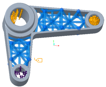
10. Open the optimized model in Creo Parametric. The cell lattice now has the optimized parameters. The model is as shown in Fig 3.
Fig. 3—Optimized model with new cell lattice parameters. | Fig. 4—Optimized model in Creo Simulate |
11. Open the model in Creo Simulate. Run the static analysis again. The total mass of the model will be displayed as 1.7348e-03 tonne which is the optimized value as calculated in the optimization study.