Example: Shell and Feature Order
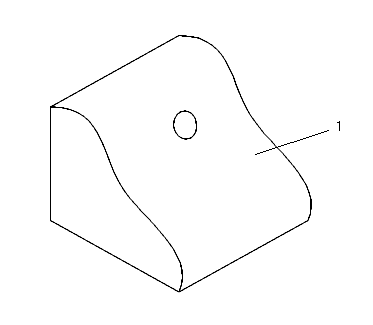
The order of feature creation is very important when you use Shell. When the system makes the shell, all the features that were added to the solid before you created the Shell feature are hollowed out. For example, the part shown in the following illustration consists of an extruded solid and a through hole.
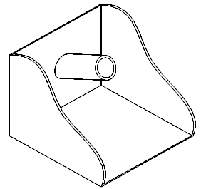
If you create a Shell feature and select the extruded spline surface (1) to be removed, the system creates a shell of constant thickness around all existing features, as shown in the next illustration.
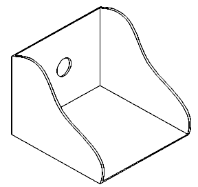
To achieve proper geometry, reorder the Hole feature to come after Shell in the model tree. The result is shown in the following illustration.


