Example: Creating a Shell Feature
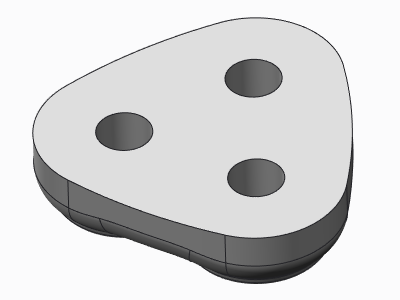
This example shows creating a Shell feature. The original part is shown in the following illustration.
1. Click
Model >
 Shell
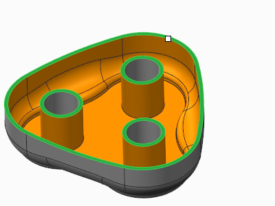
Shell. The system applies a default thickness on the inside of all the surfaces, creating a “closed” shell, and displays the preview geometry.
2. Select the top surface as a surface to remove.
3. To modify the shell thickness, type 1 in the Thickness box on the Shell tab. The system updates the preview geometry, as shown in the following illustration.
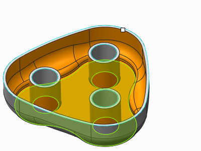
4. To specify that the bottom surface should have a different thickness, open the References tab, click the Non-default thickness collector, and select the bottom surface. The surface name and thickness value (initially equal to the default shell thickness) is added in the Non-default thickness collector.
5. Click the thickness value box in the Non-default thickness collector and type 2 to specify the thickness at the bottom. The system updates the preview geometry, as shown in the next illustration.
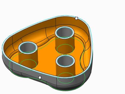
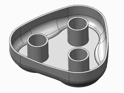
6. Click

. The final geometry is shown in the following illustration.