About Handling Rounds in a Draft Feature
Inlying rounds versus attachment rounds
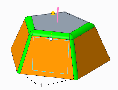
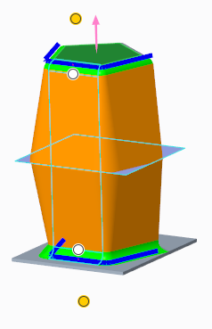
In the following image, the orange surfaces are drafted. The gray surface cannot be drafted. Two categories of rounds are shown:
• The rounds between the drafted surfaces are recognized as inlying rounds.
• The rounds between the surface that cannot be drafted and the drafted surfaces are recognized as attachment rounds.
1. Inlying rounds. All the other rounds are attachment rounds
Handling inlying rounds
When the surfaces to be drafted include rounds, there are two ways of handling the inlying rounds. The
draft_preserve_inlying_rounds configuration option defines the default of whether to preserve the inlying rounds or whether to draft them. The

command defines whether to preserve the inlying rounds or draft them for the draft feature.
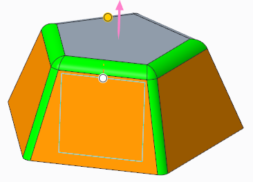
• Preserve the inlying rounds
When you preserve the inlying rounds, the draft propagates through them, but the rounds themselves are not drafted. They remain rounds.
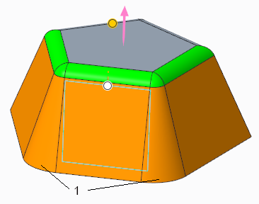
• Draft the inlying rounds
When you draft the inlying rounds, they become conic.
1. Drafted inlying rounds become conic
Attachment round or chamfer surface as hinge
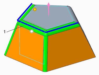
You can select one of the surfaces of an attachment round or chamfer as the draft hinge. The hinge surface must be adjacent to a surface that is selected to be drafted. The system will use the edge that underlies the attachment round or chamfer as the seed for an edge chain that defines the hinge. Along the chain, the rounds or chamfers can be of different sizes.
1. Select one surface of an attachment round or chamfer
In the draft below, a split object was used. Two different attachment rounds were selected as the hinge, one for each portion of the draft.