About Sketch Regions
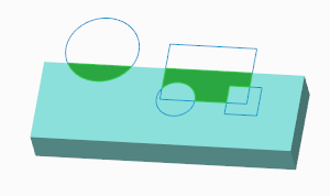
A sketch region is a quick way of selecting an area to create Extrude, Revolve, Fill, or Sketch features. It is an area enclosed by sketched curves, and edges of geometry.
These are the requirements for the boundaries of a sketch region:
• Be in the same plane
• Intersect each other
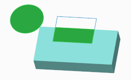
• Visible
A hidden entity can’t be a boundary for a sketch region.
You can only select a sketch region before you open a tool, in an object-action workflow. Then when you open a tool, the system automatically creates an internal sketch from the boundaries of the sketch region. The sketched curves and edges are used as references.
To select a sketch region, follow these steps:
1. In the filter list at the bottom right corner, select Sketch Region.
Alternately, use the keyboard shortcut SHIFT+S to set the filter to Sketch Region. SHIFT+G sets the filter back to Geometry.
The sketch regions highlight when you move the pointer over the geometry.
2. Select a sketch region or regions using any of these techniques:
◦ Click inside a sketch region.
◦ Click and drag a rectangle in the graphics window. Any sketch region that is inside the rectangle will be selected.
◦ To add sketch regions to the selection, hold down the CTRL key while you click each region. Clicking a selected sketch region again while you hold down CTRL removes the sketch region from the selection.
3. Right-click the sketch region, and choose a sketch-based command. The tool uses the sketch region to create geometry.