Defining the analysis measurement and tolerance chain
1. Click View > Saved Orientations > PLUG_MEASURE. The view changes to PLUG_MEASURE
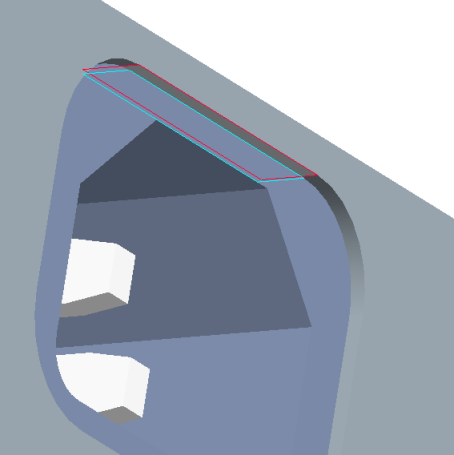
2. Select the first measurement reference: the inside top surface of the PAN cut (red surface in figure below).
3. Select the second measurement reference: the top surface of the REC-3PIN (blue surface in the figure below).
4. Select the basic locating dimension for the cut in the PAN (22.4).
5. Select the profile tolerance for the surface,

6. Select the basic locating dimension for the cut to the PAN bottom (25.2).
7. Select the profile tolerance for the surface,
8. Select on any thickness dimension of (4).
For sheetmetal dimensions, the Creo Parametric Tolerance Analysis must know the direction of the measurement with respect to the direction established when defining the analysis measurement. The analysis measurement direction is established as a vector from the first surface to the second surface. For this example, the measurement direction is as shown. Since the analysis loop is at the bottom of the PAN, the direction of the thickness dimension is opposite the measurement direction.
9. Select Opposite direction as the measurement in the Select Option dialog and then click OK.
No more dimensions are required for the PAN.
10. Click on the STANDOFF to display the next candidate dimension.
11. Select the length of the STANDOFF (15 +/- 0.1).
12. Click on the PCB to display the next candidate dimension.
13. Select the thickness of the PCB (1.6 +/- 0.1).
14. Click on the PLUG (REC-3PIN) to display the next candidate dimension.
15. Click View > Saved Orientations > RIGHT and then zoom in on left side.
16. Select the distance from the bottom of the PLUG (REC-3PIN) to the bottom surface of the receptacle (4.8 +/- 0.15).
17. Select the bottom of the receptacle to the top of the receptacle (22.0 +/- 0.15).
This completes the tolerance analysis loop.