Exercise 2: EZ Tolerance Analysis with Manual Stackup Creation
In this exercise, you will learn to manually create a stackup, to generate the reports, and save reports. Click
here to download the bearing shaft assembly. Unzip the folder in the directory of your choice.
Workflow
1. Set the default tolerance and default analysis.
2. Manually create the stackup.
3. Add a feature.
4. Generate and save the report.
Set default tolerance and default analysis
1. Click EZ Tolerance > Options . The Options dialog box opens.
2. On the inches tab, set the Linear Dimension default tolerance to 0.01.
3. Click Worst Case in the Default Analysis Type field.
4. Click OK.
Create the stackup
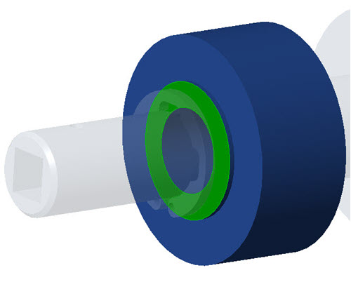
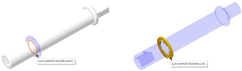
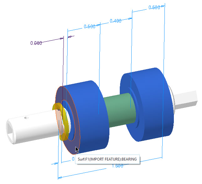
For this stackup, you will analyze the clearance between the CLIP2 part and the BEARING part.
Create the stackup: Define the stackup dimension
1. Click EZ Tolerance > New Stackup . The New Stackup dialog box opens.
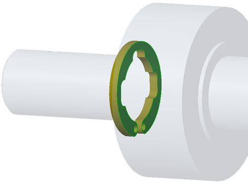
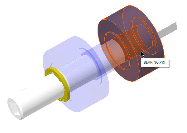
2. Select the planar surface of the BEARING closest to CLIP2.
3. Select the planar surface of CLIP2 closest to BEARING.
4. Select the ASM_RIGHT datum plane.
5. Click in the graphics window to locate the stackup dimension annotation. The Assembly Area opens in the New Stackup dialog box.
Create the stackup: Define the stackup using assembly constraints
◦ In the New Stackup dialog box, under Assembly, click Assembly Constraints and select Select in the list.
Create the stackup: Define the dimension or part loop
Follow the steps to define the part loop for the stackup.
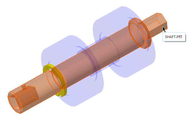
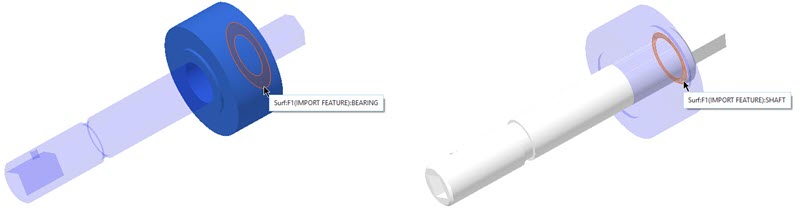
1. Select the SPACER part.
2. Select the BEARING part.
3. Select the SHAFT part.
4. Select the CLIP2 part.
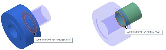
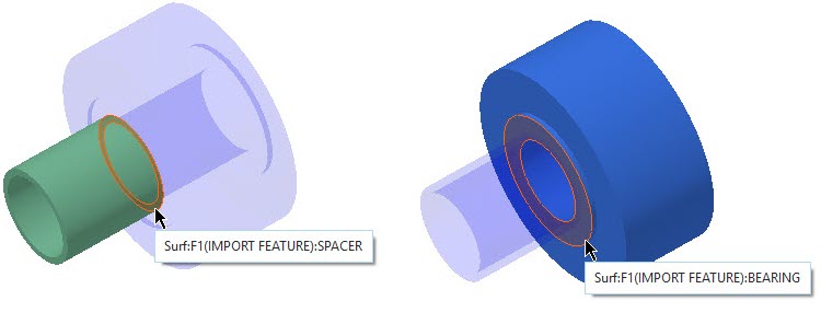
Create the stackup: Define the mating surfaces
Next, you must define the mating surfaces of the stackup. EZ Tolerance Analysis makes this easy by filtering the surfaces that are not applicable. It is recommended that you select the mating surfaces without rotating the model.
1. Select the 8 mating surfaces:
a. Surface 1 mates to surface 2
b. Surface 3 mates to surface 4
c. Surface 5 mates to surface 6
d. Surface 7 mates to surface 8
2. Click OK. The stackup is created.
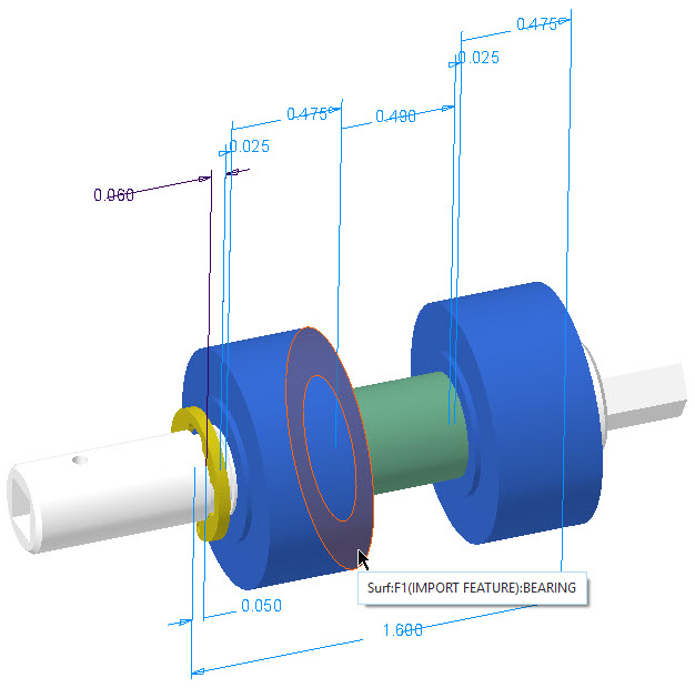
Add features
After the stackup is created, you can add intermediate features to define the dimension scheme of each part.
1. Click EZ Tolerance > Add Feature.
2. Select the BEARING step surface.
3. Select the step surface on the opposite side of the BEARING part.
4. Click OK.
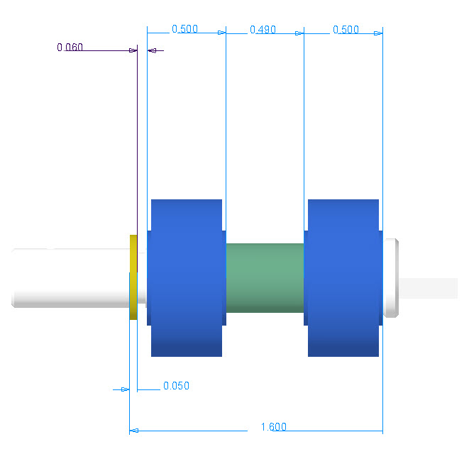
Generate and save the report
1. Close the Stackup Details table.
2. Click

in the in-graphics toolbar and select
RIGHT to reorient the model.
3. Click Stackup Table. The Stackup Details table opens.
4. Click

to save the view and size to be used in the report.
5. Click Generate Report. The Save report dialog box opens.
6. Type Report1 in the File name box and click Save.