Defining the Stackup Distance
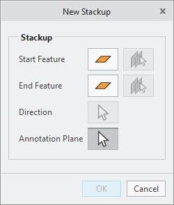
1. On the EZ Tolerance tab, click New Stackup to define the stackup and placement of the annotation representing the nominal value. The New Stackup dialog box opens.
2. Select one of the following geometry options for the stackup endpoint definition of the start feature.
◦ Planes
◦ Cylinders
◦ linear or circular edges
◦ Vertices and points
Alternatively, click

next to the
Start Feature, and then select two parallel surfaces with opposing outward normal for the start feature.
|  The arrow head changes to an icon representing the type of the selected feature. |
3. Select the geometry for the stackup endpoint definition of the End Feature. Alternatively, click
next to the
End Feature, and then select two parallel surfaces with opposing outward normal for the start feature.
| To clear the selection, click the icon representing the type of the selected feature. It changes back to  . You must perform the steps again from where you made the change. |
4. Select one of the following geometry options to define the direction, if required:
◦ Plane—Outward normal vector defines the direction
◦ Cylinder and cone—The axis defines the direction
◦ Linear edge—The direction is defined along the line of the edge
| If the direction is not determined after selecting the start and end features, select a reference such as measurement between two cylindrical features to define the direction of the stackup. |
5. Select a plane to place annotations. All dimension annotations for the loop diagram are placed on the plane you select. You can select a planar surface or a datum reference feature at any level of the model.
6. Click in the graphics window to place the annotation representing the nominal value of the stackup. You can move it to a new location, if required.