Assigning Part Types
You can assign one of part types listed below to a part. Assigning types makes the analysis more robust.
• Rivet
• Screw
• Spring
• Convex
Right-click a part in the graphics window or in the Clearance and Creepage Analysis dialog box, select Set Part Type, and select a type from the list.
Rivet
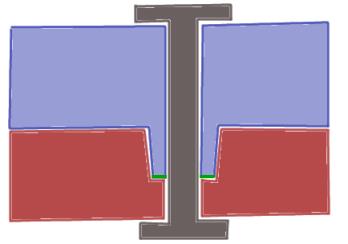
Riveted components are considered as cemented components. However, only the touching area that is directly pressed together by the rivet is considered cemented.
In the following figure the cemented area is highlighted in red:
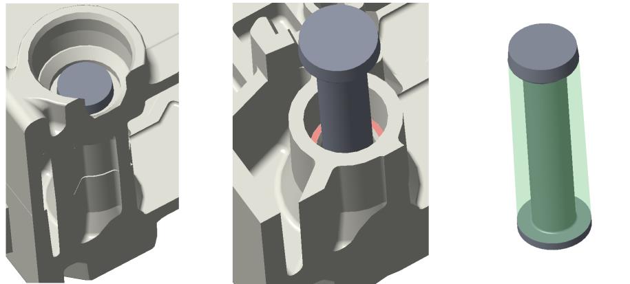
Typically, the geometry around rivets is as follows:
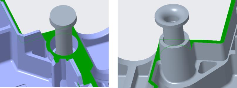
Regulations state that, only the faces that are directly between the rivet heads are considered as cemented. In the image, the faces are highlighted in green. However, the joints are still subject to creepage and clearance paths. If the two components are to be considered as cemented, you can define them as a cemented component pair. If you set the part type to Rivet, the following cementing tasks are performed automatically, otherwise it’s a manual process.
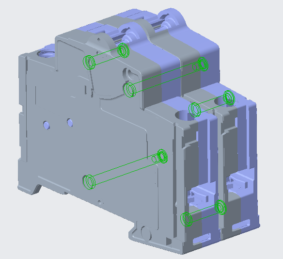
The following image shows the assembly with the rivets highlighted:
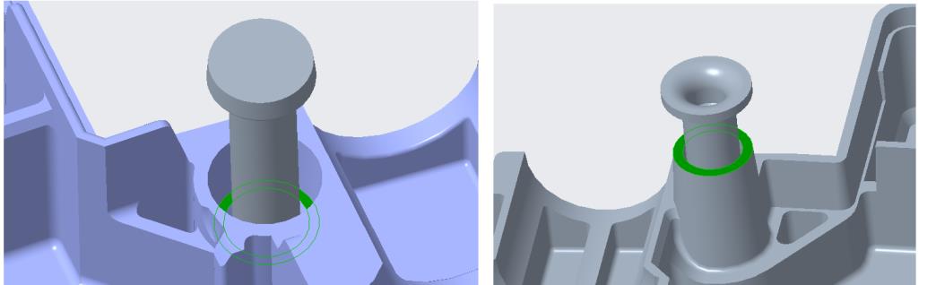
The following image shows both sides of a rivet with one of the shells hidden. When the part type is set to Rivet, the highlighted surfaces are the ones which are considered for cementing.
The surfaces highlighted in the following image are not considered cemented.
Screw and Spring
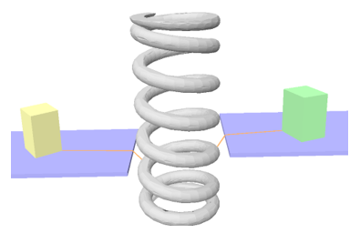
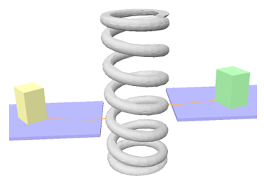
Screws and Springs are rotation variants. Their position in the CAD data may not necessarily match their position in the real-time assemblies. Rotations by a few degrees can significantly influence the analysis results. The following images show the difference in the creepage distance due to the rotation of the spring.
Creepage distance is 7.5 mm | Creepage distance is 6.88 mm |
| |
You must replace the rotation-variant conductive elements such as screw threads, polygonal screw heads, and springs with their hull for consistent results.
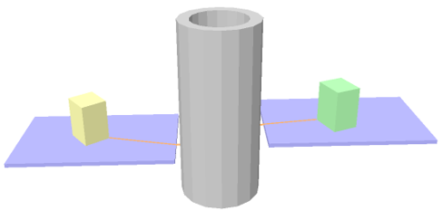
CCX automatically simplifies the geometry of parts that are tagged as screws and springs in the part list. CCX simplifies the geometry internally without changing the actual CAD data. The following image shows the internal representation of the spring when the rotation-variant conductive elements are replaced by the hull.
The creepage path is now 6.82 and is independent of the rotation of the spring.
The simplified geometry represents all possible locations of a rotation variant object. The analysis result is accurate with respect to the geometrical degree of freedom of the screw or spring.
Similar to springs, CCX replaces the internal geometry of screws with the geometry of the hull that represents all rotations around the main axis.
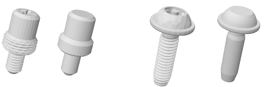
The following image shows examples of the automatic screw processing:
|  Geometry is simplified in the internal CCX optimized representation of the assembly used for the analysis. The geometry of the part remains unchanged. |
Convex Hull
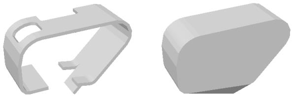
Use convex hulls for flexible, conductive parts such as clamps. Such parts have a large degree of freedom with respect to the eventual position of the flexible elements in a real assembly. Performing a creepage and clearance analysis using just a single position may be inaccurate. The convex hull represents multiple positions of the flexible elements at a time and makes the analysis more accurate.
If the part type is set to Convex Hull, the convex hull of the part is analyzed. The following image shows a clamp and its convex hull: