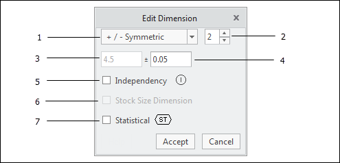
Edit Dimension (ASME)
1. Tolerance Mode — Select one of the following
tolerance modes:
◦ +/- Symmetric
◦ Plus / Minus
◦ Limits
◦ Nominal
◦ Maximum
◦ Minimum
When you select Maximum or Minimum, a MAX or MIN notation, respectively, is appended to the dimension text. These options are only available for specific dimensions for which other elements of the design determine the other unspecified limit (see ASME Y14.5-2009, par. 2.5).
2. Precision Setting — Set the desired precision (number of decimal places) for the
dimension.
3. Nominal Dimension Value — This is the
nominal value of the dimension. It cannot be changed in this dialog.
4. Tolerance Value — Specify the desired tolerance value(s). There are few conditions to consider if the tolerance mode is set to 'Limits':
◦ By default, the nominal value of a dimension in Creo is considered to be equal to the mean value of the upper and lower limits (assuming that the 'maintain_limit_tol_nominal' Creo configuration option is set to 'no', which is the default setting).
◦ If the selected dimension is a
driving dimensionAE and you change the limits such that the mean value changes, the CAD model will require regeneration.
◦ If the selected dimension is a
driven dimension AE, the limit values are disabled because the nominal value of driven dimensions cannot be changed independently.
5. Independency — When selected, Ⓘ is applied to the size dimension, indicating that
Rule #1 does not apply (i.e., perfect form is not required at MMC).
6. Stock Size Dimension — Select this option for a dimension that represents a commercial stock size (e.g., diameter of bar stock). Tolerances are not required (but are permissible) for stock size dimensions (see ASME Y14.5-2009, par. 1.4a). Keep in mind that
Rule #1 does not apply to stock size dimensions. However, if no form tolerance is explicitly specified, the applicable industry or government standard typically prescribes the limits for straightness, circularity, and other geometric characteristics. See ASME Y14.5-2009, par. 2.7.2 for more information.
7. Statistical Tolerancing — When you select this check box, the statistic tolerancing symbol,

, is added to the dimension annotation. Note that
statistical tolerancing is not well-defined in the Y14.5 standard and is not commonly used.
Dimensions in GD&T Advisor are associated with a dimension in the CAD model. When you modify the properties of a dimension in Edit Dimension, the properties of the corresponding dimension are updated accordingly. When specifying a tolerance value, it is important to consider the function of the
feature. A tolerance value is often determined from one of four different methods:
• A corporate design guideline
The tolerance values that you specify may have a significant impact on the cost of the part. You should generally specify the largest tolerance value that will meet the functional requirements of the feature.