The Axis Control Dragger
The axis control dragger enables you to apply tool axis definitions on the tool path. While creating 4 and 5– axis trajectory milling and cutline sequences, you can define axis control at a location using the At a Location option on the Axis Control tab.
If axis control at a location does not exist, the first one is created automatically when you select any one of the following references:
• A datum point
• A location on the reference edge or curve for a curve cut
• The from-to-curve for a drive surface cut
• A location on the reference edge of a cutline
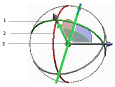
After you have made a selection and defined the required references for the cut to be created, an Axis Control Dragger such as the one in the following figure appears. It is placed on the tool path at the closest location to the selected reference.
1. Tilt Angle Rotator
2. Lead Angle Rotator
3. Tool Axis Origin
The Axis Control Dragger has the following elements:
• Lead Angle Rotator—This ring sets the lead angle and is tangent to the cut or a cutline. A positive value is applied in the direction of the cut or cutline. A negative value is applied opposite to the direction of the cut or cutline.
• Tilt Angle Rotator—This ring sets the tilt angle and is normal to the direction of the cut or the cutline. A positive value is applied to the right, based on the direction of the cut or cutline. A negative value is applied to the left, based on the direction of the cut or cutline.
The dragger takes its default orientation from the following:
• The default tool axis vector for the cut.
• The orientation of the cut or cutline in space, relative to the cutting direction.