Specifying Holder Dimensions
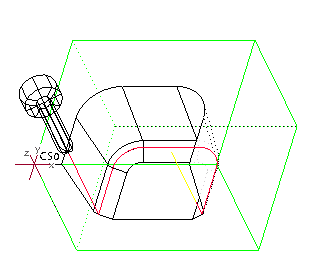
During tool setup, you can specify two holder dimensions, Holder Diameter and Holder Length. The system then adds a visual representation of the holder to the tool, both in the Preview window of the Tool Setup dialog box and when displaying CL data, as shown in the following illustration. The holder is displayed as a cylinder placed on top of the cutter.
If you specify holder dimensions, the system uses them for automatic gouge avoidance in Trajectory, Isolines Surface milling, roughing, re-roughing, finishing, and corner machining NC sequences.
When you create a solid tool model, assign the parameter names HOLDER_DIA and HOLDER_LEN to appropriate dimensions for holder identification.

