Solid Tool Capabilities in Turning
Generally, a tool model is used for visual purposes only. However, in Turning you have an option to use the tool model geometry for calculating the automatic material removal and degouging the tool path. This functionality allows you to customize the tool outline and designate the cutting edges that correspond to your particular tool/holder combinations.
When you specify that you want to use the tool outline, the system will use the whole tool profile in computing the tool path. This option is similar to using a tool model By Reference, because you can modify the tool section only by modification of the tool model geometry.
The tool model for this functionality is set up according to the general rules of setting up a solid tool model:
• It can be a Creo part or assembly.
• It must contain a coordinate system named "TIP" to indicate the control point location.
|
|
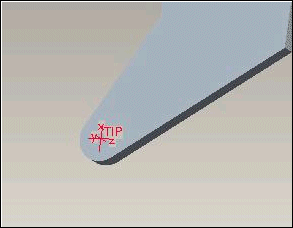
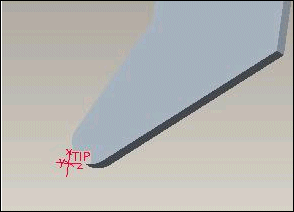
 You must define the "TIP" coordinate system such that it matches the location of the control point. The OUTPUT_POINT parameter defines the location of the control point. For example, if you place the coordinate system at the center of the nose radius, you must set the OUTPUT_POINT parameter to CENTER. The following figures illustrate the correct location for the "TIP" coordinate system when the OUTPUT_POINT parameter is set to CENTER and TIP, respectively. |
• The only geometric parameter you have to define for the tool model is Nose_Radius, required for calculating material removal. You can define this parameter by either using a model parameter or a dimension symbol. You can also add parameters to the model to provide values for non-geometric parameters (such as Tool_Comment or Gauge_X_Length). If an assembly is used as a tool model, you can use both Part and Assembly parameters for this purpose, as before. Unlike regular Tool Model functionality, you do not have to define geometric parameters (such as Tool_Width, Length); the tool outline will be based directly on the tool model geometry.
Geometry of the tool will be defined by projecting the external profile of all components of the tool model to the XZ plane of the TIP coordinate system. This projected tool contour will be used to remove material and also to degouge against the tool contour.
If the tool model is an assembly, you can indicate which portion of the tool will actually be used to remove material using the Yes_No type parameter solid_tool_cutting at the part level. If this parameter is set to yes for a certain part in the tool assembly, the outline of this part will be used as the cutting edges.
All other edges in the assembly will be assumed to be non-cutting. You can specify a clearance value, to avoid contact between non-cutting tool geometry and the workpiece material, using the NC sequence parameter TOOL_CLEARANCE. This parameter designates how close the non-cutting edges will be allowed to approach workpiece material.

