Corner Condition Types
Corner conditions are used to avoid gouging sharp convex corners, as well as to easily add necessary fillets and chamfers at the time of machining. You can specify corner conditions for trajectory milling, area turning, profile turning, and groove turning. Corner conditions are applied to geometry in Trajectory milling whereas they are applied to cut motions in turning.
The following types of corner conditions are available in Turning and Trajectory milling:
• Sharp—A corner which has no chamfer and or corner radius.
• Fillet—A fillet which can be added both at concave and convex corners. The fillet radius is defined by either the Concave Radius or the Convex Radius values, depending on the type of the corner.
Note the following about convex and concave fillets in Trajectory milling:
◦ Convex Fillets—The corners on the tool path remain sharp as long as the concave radius is less than or equal to half the cutter diameter. When the concave radius exceeds the cutter diameter, the radius is equal to CONCAVE_RADIUS – 0.5 * CUTTER_DIAM. This change in radius is clearly visible at the corners on the tool path.
◦ Concave Fillets—The radius on the tool is equal to CONCAVE_RADIUS + 0.5 * CUTTER_DIAM
• Chamfer—A chamfer which can be added both at concave and convex corners. The chamfer size is defined by the Chamfer Dimension value, which represents the distance cut on each side of the corner. The chamfers on the tool path are based on the following parameters:
◦ The chamfer length.
◦ The type of corner, which is either convex or concave.
◦ The angle formed by the walls in the corner.
• Loop—This condition is applicable only in trajectory milling. The condition is valid only for convex corners and the radius is specified using Convex Radius.
• Straight—This condition is applicable only in trajectory milling and creates a parallelogram corner condition on convex corners to preserve a sharp edge. The length of the cut is defined using Corner Length and the angle of the parallelogram is specified using Corner Angle.
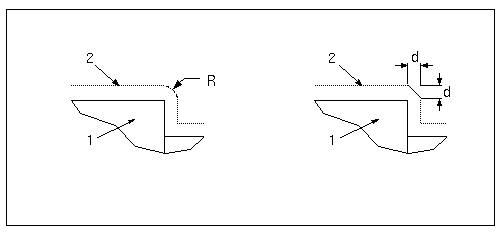
The graphic below illustrates the corner condition types.
Schematic on the left shows the Fillet corner condition, with R = Convex Radius. Schematic on the right shows the Chamfer corner condition, with d = Chamfer Dimension. In both schematics:
1. Reference part
2. Tool path
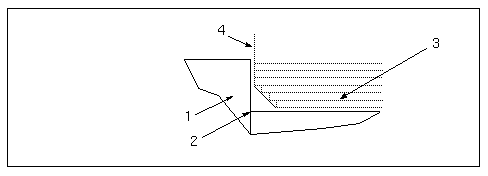
For Area turning, both the rough and profile passes will take the corner condition into account, as shown in the following illustration.
1. Part
2. Chamfer corner condition added here
3. Rough passes
4. Profile pass


