Corner Condition Types
Corner conditions can be specified for the vertices of the cut motion created using the Edge or Curve option, to avoid gouging sharp corners. Wherever a corner condition is added, a small parallelogram will be incorporated in the cut motion: the tool will continue moving along the first entity, then return to enter tangent to the second entity. The size of the parallelogram is defined by the path parameter CORNER_LENGTH.
If you add a corner condition along an entity or between two tangent entities, the angle of the parallelogram will be defined by the CORNER_ANGLE parameter; if the condition is at a vertex and the corner is sharp, the CORNER_ANGLE value will be ignored and the sides of the parallelogram will be formed as a continuation of the adjoining entities.
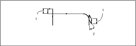
The following graphic illustrates the CORNER_LENGTH and CORNER_ANGLE parameters.
1. CORNER_LENGTH
2. CORNER_ANGLE
The following corner condition types are available:
• Straight—Create a straight corner condition.
• Concave—Create a round corner motion for a corner that is concave.
• Convex—Create a round corner motion for a corner that is convex.
• Chamfer—A chamfer whose size is defined by the CHAMFER_DIM parameter, which represents the distance cut on each side of the corner.
• Fillet—Create a fillet corner motion.
• Loop—Create a loop corner motion. Available for convex corner conditions only.

