About Light Icons
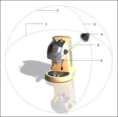
Light icons are used to show the position and direction of a light type. When you activate a light in the Light List in the Lights tab in the Scene Editor dialog box, its icon is displayed in the graphics window and you can manipulate the light's parameters directly from the graphics area. You can also show the inactive lights in the graphics area by selecting the Show Light check box in the Lights tab for the respective light type. The following types of lights have light icons:
• Lightbulb—Represents the light position. The color of the light is indicated by the color of the lightbulb.
• Distant—Consists of the position of the light and an aim point with a direction line. The color of the light is indicated by the color of the bottom face of the distant light.
• Spotlight—Consists of the light position, an aim point, a direction line, an arrowhead focus angle, and a spread angle cone. The color of the light is indicated by the color of the cone's bottom face.
Lightbulb 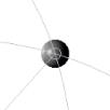 |
Distant Light 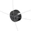 |
Spotlight 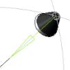 |
Light is updated dynamically as you manipulate the light icons in the graphics window. An active light has a larger light icon when compared to inactive lights. The size of the light icons also depends on the size of the model. Depending upon the type of light, the light icons have a maximum of four components: Source Location, Aim Point Location, Focus, and Angle.
You can select the lights by clicking on the light icons in the graphics window. A light icon has the following controls:
• Light Source Point Controls—This zone controls the X-, Y-, and Z-coordinates (with respect to the screen) of the light source location under Source Location in the Light Position dialog box. You can manipulate the following entities to modify the light source point:
|
Sphere
|
• The light source point is located at the intersection of the 2 polar rings. You can move it along the surface of an imaginary sphere.
• The source point component is highlighted when you move the pointer over it and while dragging.
• The sphere is divided into front and back hemispheres by an imaginary plane that is parallel to the screen.
• While dragging, when the pointer leaves the sphere's silhouette, the point movement continues onto the rear side of the sphere. You can do the same to come back to the front side.
• You can change the size of the sphere by dragging the sphere’s silhouette. The silhouette edge of the sphere is highlighted when you move the pointer over it and while dragging.
|
|
The 2 Polar Rings
|
• Holding the light source point, you can rotate the polar rings about the X- and Y-axis of the screen. You can also move the light source along the ring path by selecting and dragging either of the rings.
• When the light source point is located in front of the sphere, only the front portion of the ring is displayed.
• When the light source point is located behind the sphere, only the back portion of the polar rings is displayed as dashed lines.
• Drag the ring to change the size of the sphere and the location of the light source.
• The rings are highlighted when you move the pointer over them.
|
1. X-axis ring (Polar Ring)
2. Sphere's silhouette
3. Y-axis ring (Polar Ring)
4. Light Source
5. Direction Line
6. Aim Point
• Aim Point (Center of sphere)—This zone corresponds to the X-, Y- and Z-coordinates of Aim Point Location in the Light Position dialog box.
◦ The aim point location is highlighted when you move the pointer over it and while dragging.
◦ A line connects the aim point location and the source point of the light to indicate the direction of the light. The color of the line is also that of the light. You can move the entire sphere by dragging the direction line. In case of a spotlight, drag the black portion of the direction line to move the sphere. For other types of lights, you can move the entire direction line to move the sphere.
|  In case of the lightbulb, the black line does not indicate direction of the light, because this light throws light in all directions. This line in case of the lightbulb and the skylight is used to move the entire sphere. You can position the aim point location in the following ways: • You can freely drag the aim point location parallel to the screen (X- and Y- axis, no Z-axis). • Based on model geometry—Hold down the SHIFT key and drag the aim point location. The aim point snaps to any geometry immediately behind it. |
In addition to the above controls, the spotlight also has the following controls:
• Spread Angle for Spotlight
◦ The base edge of the spotlight is highlighted on moving the pointer over it.
◦ You can drag the base edge of the spotlight cone normal to the direction line to control the value of the spread angle of the spotlight.
• Focus Arrow for Spotlight
You can also change the focus angle of the spotlight by dragging the arrowhead of the aim point direction line. The longer the arrowhead, the sharper is the focus of the spotlight.