|
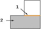
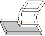
Bend Line Sketch
|
||
 |
||
|
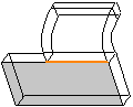
Bend One
|
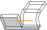
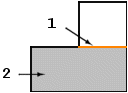
Bend Two
|
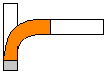
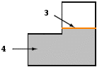
Bend Three
|
  |
  |
  |
|
Bend Line Sketch
|
||
|
||
|
Bend One
|
Bend Two
|
Bend Three
|
|
|
|

Non-coplanar Surfaces | Coplanar Surfaces |
 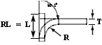 |  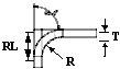 |
BLA = L - ( R + T ) | |
Where: BLA = Bend line adjustment L = Developed length of the bend (determined from a bend table or formula) R = Inside radius of the bend T = Thickness RL = Relief length ( = cutback length in rip relief) | |