Using Networks to Route Cables
A network is a series of locations that defines default paths to automate the process to route cables. While routing a cable through a network, the application routes the cable along the network using the shortest calculated path. Cables can only enter and exit a network path through a network location.
While creating network paths, avoid closed loops. A closed loop network can create issues in Harness Manufacturing.
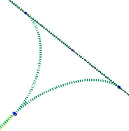
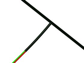
You can remove closed loops by creating T-Branch when necessary. The following image illustrates an example of closed loop network that can be removed by creating a T-branch bundle.
Network Bundles
Network bundles and sheathing are created in the same way as other bundles, except that they exist along a branch of the network. You can assign bundles and sheathing to network segments even if no wires are present.
Sheathing on the network can be used to plan space for the harness in early stages of the design.
To Create a Network
This topic describes the procedure to create a network to route cables. A sample cabling assembly displaying already created networks is provided. You can view the videos along with the sample file to understand how to create networks for the most efficient harness routing.
1. Click
 Route Network
. The Route Network tab opens and a new network is created in the Model Tree.
2. Click a reference in the graphics window to place the first network location.
3. Click again to place a second location. A segment connects the two locations.
|  To place network locations at each end of an axis, for example through a hole, select the axis, right-click and click Along from the shortcut menu. You can also change the configuration option default_cable_axis_location to ALONG. By default, the default_cable_axis_location configuration option is set to ON. |
4. Continue placing locations to create the network.
5. To create a branch, select a location on the network and click to place the next branch location.
| While placing locations near the connectors, it is always recommended to leave some gap for effective routing. |
6. Click

.
To Create an Offset Location
1. Create a new network location.
| You cannot create an offset location for the first location. |
2. Follow one of the following procedures:
◦ Using the Next Location option:
1. Right-click and click Next Location > Offset from Point and select a reference point.
2. Right-click and click Next Location > Offset from Previous and select a previously placed location as the reference location.
3. Select a coordinate system or three references for three axes.
4. Double click a value and type a new value to place the location.
Or open the Placement tab and type new values for the Offset References.
◦ Using a vertex or coordinate system:
1. Select a vertex or coordinate system in the graphics window.
2. Change the type in the Type list to Offset.
3. Select a coordinate system or three references for three axes.
4. Double click a value and type a new value to place the location.
Or open the Placement tab and type new values for the Offset References.
5. Click again to place a new location.
| • If you do not want the network to have any assembly references, you can remove all assembly references by converting the locations to reference from a csys (Locations > Convert to Offset). • To ensure that the overall diameter of a harness path does not exceed a specified diameter, specify maximum bundle diameter at network location. Wires that exceed the specified diameters use alternate paths. |
To Edit a Network Segment
1. Select a segment in the Model Tree or graphics window, right-click and click

. The
Location tab appears.
2. Select a location on the network and drag it to the desired location. To know more about Location Properties, click
here.
3. Click
to exit edit mode.
To Check Network Continuity
Click Check Continuity. Network continuity is checked and an appropriate message is displayed as follows:
• If the network is continuous, a message indicating that the network is continuous is displayed.
• If the network is not continuous and the number of network sections present is between two and eight, a message indicating the number of network sections is displayed and all the network sections are highlighted in different colors.
• If the network is not continuous and has more than eight sections, a message indicating the number of sections is displayed and only eight sections are highlighted in different colors.
To Check for Overlapping Locations
Click Check Locations. Overlapping locations are checked and an appropriate message is displayed as follows:
• If no overlapping locations are found, a message indicating that no overlapping locations are found is displayed.
• If overlapping locations are found, a message indicating the number of overlapping locations is displayed and the locations are highlighted. You are prompted to merge all the overlapping locations into single locations. If you click Yes, all overlapping locations are converted to single location points and the network reroutes sections that are involved through single location points.
To Share Networks Between Harness Parts
Sharing makes a network created in a non-active harness available to the active harness.
1. Click Route > Share Network > Share.
2. Select the harness with which you want to share the network. The model is regenerated and the locations in the shared network are available to the current harness.
◦ To directly connect networks across shared harness parts, use the Route > Share Network > Connect command.
◦ To undo the sharing, use the Route > Share Network > Unshare command.