Splices and Inline Connectors
About Adding Components to the Cable Path
You can add the following components to a location along the cable path, between the two cable-terminating entry ports:
• Splice components—These are components added along the length of a cable. The cable name and the length from connector to connector is not affected after the splice component is installed. You can insert both Through and Butt type of splice components that are created in Diagramming.
• Custom components—These are similar to splice components, except that they do not use parameters. You can use custom components for cabling objects that do not need a reference designator.
• In-line connectors—This is a pair of male and female connectors that break the cable into two physical cables but maintain signal continuity between them. The connector assembly must have an assembly-level coordinate system on either side representing an entry point and an exit point. When placed on an existing cable it splits the cable into two separately named entities. The length of each entity is calculated from the entry or exit location point. To add internal lengths, use the entry port parameter int_length on the component.
To Insert a Splice or Custom Component
Refer the
cabling_assembly.asm sample assembly to learn how to insert a splice or a custom component in the cabling model. Sample models are available at
<Creo load point>\Common Files\help\sample_models\cabling. Open
cabling_assembly.asm. Set
INSERT_SPLICE as the working harness. Select
INSERT_SPLICE from the
 Saved Orientations
 list.
1. Click
 Insert Component
. The
Place Component and the
Open dialog boxes open.
2. In the Open dialog box, select a part or an assembly and click Open. You can select a part that has only a surface or datum curve or at least a datum coordinate system to define the entry ports. The selected part or assembly appears in the Component Window and it appears in a separate window in the Model Tree.
In the sample assembly, select Splice.prt and click Open.
3. In the Place Component dialog box, select the component type. If you select Custom as the component type, you cannot select a reference designator.
In the sample assembly, select Splice as the component type.
4. Select a coordinate system from the model displayed in the Component Window or select a coordinate system from the Model Tree. The selected coordinate system appears in the Entry port box of the Place Component dialog box.
In the sample assembly, select ENTRY_1 from the splice Component Window.
5. Select the constraint type.
◦ Tangent to cable—Attaches the attachment coordinate system to the location selected earlier with its z-axis tangent to the cable segment at the location.
◦ Perpendicular to plane—Attaches the splice or custom component selected to the selected Plane, Crv/Edg/Axis, or Csys from the GEN SEL DIR menu. The z-axis of the coordinate system is normal to the selected plane or aligned to the selected curve, edge, axis, or coordinate system. You can modify the direction of the attachment location to be parallel to the z-axis of the attachment entry port.
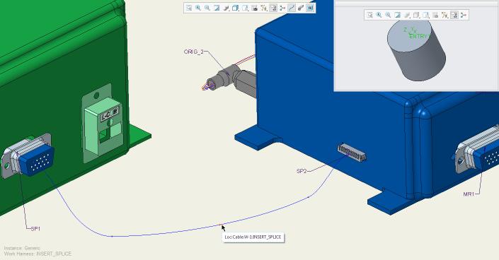
6. From the Graphics window select an existing location where you want to place the component. The selected location appears in the Cable location box.
In the sample assembly, select the location as shown in the figure.
7. Specify the reference designators.
◦ Select ref des—Click Select ref des and select an existing reference designator from the list.
◦ Create ref des—Click Create ref des to create a new reference designator.
In the sample assembly, click Create ref des.
8. Click OK in the Place Component dialog box. The component is placed at the specified location and the ORIENT COMP menu appears. This menu determines the orientation of the component.
9. Specify the required orientation.
◦ Flip—Changes the orientation from the positive-z to the negative-z of the coordinate system, or vice-versa.
◦ Twist—The TWIST menu appears.
▪ Set Ref Port—Prompts you to select a port on the cable centerline as a zero reference.
▪ Set Zero Ref—Prompts you to select an edge or axis to use as a zero reference for the twist.
▪ Clear Zero Ref—Clears the zero reference and twists the component relative to the current position.
▪ Enter Value—Opens an input box. Type a value of rotation.
▪ Align X—Aligns the x axis of the component's port with the geometry reference.
▪ Align Y—Aligns the y axis of the component's port with the geometry reference.
10. Click Done. The Setup Cable Paths dialog box opens. The Component items section displays the name and the path, which is the entry ports, of the cables that touch the component.
11. To modify the path of a cable, select it in the list. The Items to modify section display the entry and exit information for each network segment. You can, therefore, control every network segment.
In the sample assembly, select W-1 under Component items. The wire W-1 displays under the Items to modify section. Under Path, click Exit and select the exit port ENTRY_2 from the graphics window.
12. Under Show, you can set and modify the visibility of cable paths inside a splice:
◦ Yes—The internal segment for a cable is displayed between the entry and exit location in the 3D view.
◦ No—The wire display terminates at one entry port and resumes at another entry port. This option is selected by default.
◦ As is—The visibility of the cable path remains unchanged.
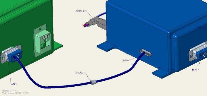
13. Click OK. The component is inserted into the cable path.
| • The minimum bend radius is ignored for internal segments. Cabling assumes that the selected path is the shortest path that maintains tangency between the entry and exit z-axis unless the internal path has and shows manually added locations. • Harness Design cannot flatten loops. However, it can flatten the internal portions of splices and components even if they form a loop. Harness Design can also flatten a virtual loop. • Whole cables cannot enter the component while individual conductors exit the components. Bundles must stop at the last location that is common to all cables. A new bundle that is manually created cannot continue after the component unless all cables in the bundle enter and leave together. • If the item goes into a component and does not stop at an entry port, it must come out as itself, and not as part of a cable or bundle. Items that go in and continue must exit as well. |
To Insert Multiple Splices at a Single Location
1. Click
Insert Component. The
Place Component and the
Open dialog boxes open.
2. In the Open dialog box, select a part or assembly and click Open. You can select a part that has only a surface or datum curve or at least a datum coordinate system to define the entry ports. The selected part or assembly appears in the Component Window and it appears in a separate window in the Model Tree.
3. Select the attachment entry port on the model being assembled.
4. Select a coordinate system from the model displayed in the Component Window or select a coordinate system from the Model Tree. The selected coordinate system appears in the Entry Port box of the Place Component dialog box.
5. Select Splice as the component type.
6. Select the constraint type.
◦ If you select Tangent to cable, the attachment coordinate system attaches to the location that you selected earlier with its z-axis tangent to the cable segment at the location.
◦ If you select Perpendicular to plane, select a Plane, Crv/Edg/Axis, or Csys from the GEN SEL DIR menu as a constraint to assemble the splice or custom component. The z-axis of the coordinate system is normal to the selected plane or aligned to the selected curve, edge, axis, or coordinate system. You can modify the direction of the attachment location to be parallel to the z-axis of the attachment entry port.
7. Select an existing location for the component in the Cable location box.
8. Select an existing reference designator or create a new one. To select multiple reference designators, hold down the SHIFT or CTRL key and select the required reference designators.
9. Click OK. Multiple splices are placed at the selected location.
|  If you insert multiple splices at a location using this procedure, you cannot modify the orientation of the individual splices. To modify the orientation of the splices, insert single splices and not multiple splices. |
To Insert an Inline Connector
1. Click
Insert Component. The
Place Component and the
Open dialog boxes open.
2. Select a part or assembly and click Open in the Open dialog box. The selected part or assembly appears in the Component Window and also appears in a separate window on the Model Tree.
3. Select the attachment entry port on the model being assembled.
4. Select a coordinate system from the model displayed in the Component Window or from the Model Tree. The selected attachment entry port appears in the Entry Port box of the Place Component dialog box.
5. Select In-line connector as the component type.
6. Select an existing reference designator or create a new one. If you do not specify a reference designator, the part name is used as the reference designator.
7. Select the constraint type.
◦ If you select Tangent to cable, the attachment coordinate system attaches to the earlier selected location. The z-axis of the coordinate system is tangent to the cable segment at the location.
◦ If you select Perpendicular to plane, the GEN SEL DIR menu appears. Select Plane, Crv/Edg/Axis, or Csys as the constraint to assemble the in-line connector. The z-axis of the coordinate system is normal to the selected plane or aligned to the selected curve, edge, axis, or coordinate system. You can modify the direction of the attachment location to be parallel to the z-axis of the attachment entry port.
8. Select an existing location for the component in the Cable location box.
9. Click OK in the Place Component dialog box. The component is placed at the specified location and the ORIENT COMP menu appears. This menu determines the orientation of the component.
10. Specify the required orientation.
◦ Flip—Changes the orientation from the positive-z to the negative-z of the coordinate system, or vice-versa.
◦ Twist—Type an angle value and change the orientation of the splice or component by aligning the x- or y-axis of the attachment entry port to a selected reference. A dimension is created for the twist.
11. Click Done or Quit. You are prompted to name one of the new wires that you have created. The new wire is highlighted.
12. At the prompt, type a new name for the wire. The other section of the wire is highlighted and you are prompted to name it.
13. At the prompt, type a name for this section of the wire. You are prompted to select another entry port on the splice.
14. Select the second entry port on the other side of the connector assembly. A new location is created for the exit point.
15. If there are any locations inside the connector, manually delete them.
| Cable lengths are calculated from the originating terminals to the inline connector's coordinate system of the entry port. To add internal lengths, use the component entry port parameter, int_length, on the inline connector. |
To Delete a Splice or Component
1. Click
Component >
 Delete Component
. The
DELETE/SUPP and
SELECT FEAT menus appear. By default,
Select is selected.
2. Select one of the following commands from the DELETE/SUPP menu:
◦ Normal—Deletes or suppresses selected features.
◦ Clip—Deletes or suppresses selected features and all features created later.
◦ Unrelated—Deletes or suppresses all features other than those selected.
3. Select one or more components to delete and click Done in the SELECT FEAT menu.