![Integration Kit What's New [Integration Kit What's New]](../Nav02_WhatsNew.png)
![Integration Kit What's New [Integration Kit What's New]](../Nav02_WhatsNew.png) |
The models produced within Creo Elements/Direct Modeling today can represent the geometry of the parts and assemblies that make up a product design, but we cannot manufacture the part from this 3D model.
Manufacturing a part requires more than just the geometry; it requires
information about the design intent and the manufacturing, finishing
and assembly processes and steps required to produce the part. Today
additional steps are required to generate 2D drawings and other
documentation to detail the manufacturing processes and assembly steps for
producing a product. Much of this effort involves the regeneration of the
product design in these redundant documents.
Design Information features provide a framework for defining and customizing
features which document the design and manufacturing information for a
product. They provide mechanisms for:
Design Information features can be attached to any level of objects or
elements in Creo Elements/Direct Modeling. This includes Assemblies, Parts,
Workplanes, Workplane-sets, Faces, Edges, and Vertices. These features may
be viewed on the 3D model in the graphics viewport and may also appear in
the Structure Browser. The user can generate HTML reports of all or selected
subsets of Design Information features.
A Design Information feature is defined by an SD-DEFFEATURE specification. This is a LISP macro which defines all of the key attributes of the feature including:
The feature definition is required to be loaded for the create, modify and copy operations. If a Design Information feature already exists on a model, but its feature definition is not loaded, Creo Elements/Direct Modeling will automatically try to load its definition when a modify or copy operation is requested. The feature definition will be attempted to be loaded from either the :src-location URL or the :alternate-location URL if it exists. A feature definition can be manually loaded via the load command from either a local source or via a URL (using the sd-retrieve-url function):
(load "c:/users/joe/PTC/DesignInfos/paint.lsp")
(load (sd-retrieve-url "http://www.ptc.com/sd/designinfo/examples/paint.lsp"))
A feature is composed of a number of important components. Some of these components are defined by the feature designer and fixed for each kind of feature. Others are controllable or assignable by the user.
This attribute automatically maintains the validity status of the feature. There are 3 values for this attribute:
The feature type attribute of a feature has two possible values: :geometric and :non-geometric. The feature type affects how the feature reacts to events such as 3D modification events. The types and their behaviors are defined as:
The owner of a feature is always a 3D object. The owner is important because it controls when and how a feature will be filed. The owner depends on the type of feature (geometric or non-geometric) and the item or items to which the feature is attached (the attachments). The owner is not controllable by the user, but is determined by the attachments which are defined either directly (for non-geometric features) or indirectly (for geometric features) by the user.
Geometric features: Geometric features are always attached to 3D faces on a body. The feature may have any number of faces attached to it. The owner is the Part (or parts in the case of shared bodies) that owns the body.
Non-geometric features: Non-geometric features may be attached to either
The feature behavior properties are attributes of a feature that are defined by the feature designer. The behaviors define how the feature responds to various events and conditions. The behaviors include:
The appearance properties of a feature specify the feature's definition and appearance. These properties are specified by the feature designer, but they can be overridden by a local feature administrator via the sd-cust-feat-local-appearance function. The feature definition properties include:
Each feature maintains its own transformation matrix. Transforms such as translations and rotations are maintained in the transformation matrices of the owning 3D objects. However, a feature maintains its own local scaling transformation.
A key component of every feature are the feature variables. It is these variables that contain the design information that the feature represents. The feature variables and variable types are defined by the feature designer. However, the values of the feature variables are specified by the user. There are two important kinds of feature variables: value variables and reference variables.
Value variables: These are variables that maintain a user specifiable value. The values of these variables may be affected by transformations of the owning 3D objects or the feature itself. These values are automatically transformed and corrected for the user's units when appropriate. Some variable types such as strings and (unitless) numbers are not transformed, whereas others such as lengths, angles, points, directions, etc. are transformed. Modeling operations performed by the user (such as 3D Align, 3D Taper, Anisotropic scaling, etc.) will cause these values to get out of sync with the geometry for geometric features. In such cases the feature will be invalidated. The user must then revalidate it by modifying the feature.
Reference variables: Reference variables are variables that reference elements on a body (3D elements) or profile (2D elements). These references are not affected by transformations of the owning 3D objects or the feature itself. However, the feature will be invalidated if the referenced element is destroyed. The reference variable is represented by a SEL-ITEM within Creo Elements/Direct Modeling, and a simple string name for the element in the VRML file and HTML report.
Each feature may have a label for identification and selection of the feature from the graphics viewport. The feature designer specifies whether a feature will have a label, and if so, how the label text is generated. This is specified in the :label-str attribute. The label text may be either fixed text, or dynamically generated based on one or more of the feature's variables. Any characters can be used in the label for a feature. The feature label can also include special symbols from the hp_symbols and hp_syms2 font sets via special shift-in and shift-out characters (16/17 for the hp_symbols font and 30/31 for the hp_syms2 font). When a feature has a label, the default is for the label to be displayed. The visibility of individual labels can be controlled by the user through the Show command. The visibility of all labels can be controlled by the user through the Viewport's Sh menu.
Features which are attached to a body (Part by contents) may have a name for identification and selection of the feature from the structure browser. The feature designer specifies whether a feature will have a name, and if so, how the name text is generated. This is specified in the :name-str attribute. The name text may be either fixed text, or dynamically generated based on one or more of the feature's variables. A feature name can consist of only alphanumeric characters or the characters '_', '-', and '.'. Any other characters are converted to an underscore ('_'). Feature names must unique to a 3D object, thus a numeric suffix may be appended to a feature name to make it unique.
The user can change the name of a feature with the Rename command. When a feature is transported from one part to another by operations such as unite, the feature may need to be re-named to ensure that all features have a unique name. To account for user modified names, the feature's current name will be used as the prefix, rather than the :name-str.
Each feature will have a dialog box as specified by its feature definition to control the specification of its variable values by the user. The feature definition (and hence the dialog definition) must be available in order to create, modify or copy the feature. The dialog name for a feature is the concatenation of the feature's :package name attribute and it's feature name attribute - both defined by the feature designer.
There are three modes of feature construction: :create, :modify and :copy. The same SD-DEFDIALOG is used for all three operations with a mode flag set to distinguish the current operation. The following process is used by the dialog to create the new feature:
Feature labels have several attributes that control their appearance. All of the attributes may be changed at any time through the commands in the Properties sub-menu of the Features menu. The label attributes are:
The default anchor, position and orientation attributes are determined automatically based on the elements that make up the feature. These attributes of a label may change whenever the feature is modified. These attributes are determined as:
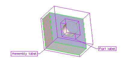
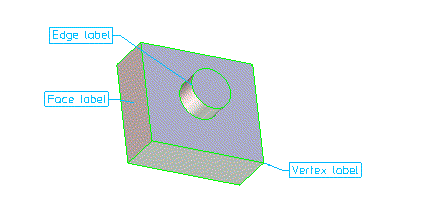
The font, size, color and framing of the label are attributes of the label, not attributes of the feature. They are not specified directly in the feature definition, but are set to default values when the label is created. They may be set independently for each label at any time through the Settings sub-menu of the Properties menu. The values of these label attributes are maintained when a feature is modified.
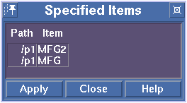
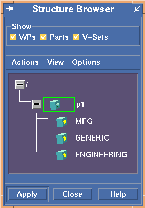
Many feature operations require the selection of one or more existing features. The Modify and Copy operations, for example, require the selection of a single feature, while the Report, Highlight, and Show operations will allow multiple features to be selected. There are 4 ways to select a feature:
The feature designers control the organization of the features they write by specifying the categories to which the feature belongs. Each feature must specify a list of categories. If a category is new, then the category paths are added to the category tree. The feature is then added to the tree under all appropriate categories. Features are reported in the HTML report sorted and filtered by category. By specifying multiple categories for a feature, the feature designer can allow features to be reported using different sorting and filtering criteria. The category specifications thus create non-exclusive groupings of features.
The category specifications for a feature can be modified by a local feature administrator to account for local report requirements. This is accomplished by over-riding the :category property for a feature using the sd-cust-feat-local-appearance function.
The category tree including the loaded features is displayed in the Design Infos Browser when the Create command is started. An example of this browser is shown below. Note that the feature "Tap Hole" is specified in two categories: "/Documentation" and "/Mfg/machining".
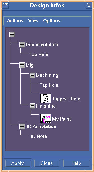
The Design Infos Browser is also displayed for the Report command when filtering by category; however, in this case the category tree is displayed without the features.
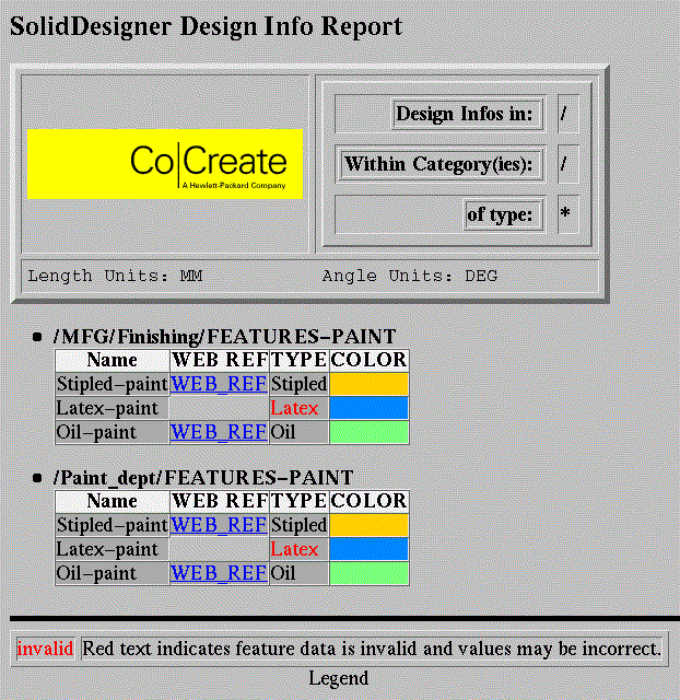
The Design Information feature report produces an HTML document summarizing a set of user specified features. This report consists of report header and a list of report tables with features sorted by category. The report header contains the following information:
The report tables consist of:
If a feature belongs to more than one category, it may show up in more than one table in the feature report. Some special attributes of the report tables are:
An example feature report is shown below:
Features are written using the SD-DEFFEATURE macro. They are written in LISP as text files, but can be compiled using the Creo Elements/Direct Modeling LISP compiler along with a C++ compiler. The SD-DEFFEATURE interface defines a set of attributes for the feature. These attributes can be divided into 4 groups:
There are also several LISP functions that can be used in writing the feature:
Finally, a local administrator can set up local feature appearance attributes by using the SD-LOCAL-APPEARANCE function. This function installs local appearance attributes which override those specified in the feature definition.
![Integration Kit What's New [Integration Kit What's New]](../Nav02_WhatsNew.png) |
| © 2024 Parametric
Technology GmbH (a subsidiary of PTC Inc.), All Rights Reserved |