![[Integration Kit What's New]](../Nav02_WhatsNew.png "Integration Kit What's New")
| |
Dialogs are the means how a Creo Elements/Direct Modeling user interacts with the system. A dialog is typically started by the user, who then specifies the necessary input. The user is guided by the system, that helps him by providing the right input tools, by checking and verifying input. Then, mostly after pressing the "Ok" button, an appropriate action is started.
Dialogs in Creo Elements/Direct Modeling can as well be executed by just entering the dialog name and the appropriate parameters in the command line or in a program.
Creating dialogs is one of the main tasks when developing add-on application to Creo Elements/Direct Modeling.
The Dialog Generator is the tool to help you doing so. The Dialog Generator also ensures, that user defined dialogs (also referred to as user defined commands or UDCs), look and behave like existing Creo Elements/Direct Modeling dialogs.
It also creates the command line input functions for the new dialog.
The Dialog Generator is a tool, that helps the programmer to concentrate on the "what" instead of the "how" of programming a dialog. A dialog is programmed by just specifying the types of data, that are required from the user and by then executing one or more Creo Elements/Direct Modeling commands.
The programmer does not have to take care of how to get the Creo Elements/Direct Modeling look and feel, of error and value type checking, of unit conversions, or button sizes and colors: all that is done by the Creo Elements/Direct Modeling Dialog Generator.
In order to understand the functionality of the Dialog Generator, the following example will demonstrate the principles:
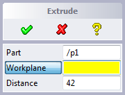
The user is presented a command button in the Creo Elements/Direct Modeling toolbox. After clicking the button, the dialog options are displayed within a task bar panel.
The user is now free to in parallel specify all the necessary input. The user may choose to re-enter an input, if it is not correct. Hitting "Ok" will complete the dialog and an action is executed. Hitting "Cancel" will abort the operation. Hitting "Help" will present context-sensitive help to the user.
The following chapter will present you a first example, which demonstrated the basic concepts of the Dialog Generator.
(use-package :OLI)

(sd-defdialog 'my_extrude
  :variables
  '((A-PART :value-type :part-incl-new)
    (A-WP :value-type :wp-with-profile)
    (DISTANCE :value-type :distance :initial-value 42))
  :ok-action
  '(sd-call-cmds
    (extrude :part a-part :wp a-wp :distance distance)))
This is the Lisp code of a dialog in a Lisp file.
  :variables
  '((A-PART :value-type :part-incl-new)
    (A-WP :value-type :wp-with-profile)
    (DISTANCE :value-type :distance :initial-value 42))
The possible user input consists of three different options, which are represented by three variables in the code. All are specified by type and some possible options like the initial value, prompting text, ... By using these information the Dialog Generator then creates the corresponding button in terms of shape, behavior, prompting and error checking.
  :ok-action
  '(sd-call-cmds
    (extrude :part a-part :wp a-wp :distance distance)))
After having collected the user input, several actions can be specified. An action can e.g. occur immediately after the input, after pressing the "Ok" or "Cancel" buttons or even during the input operation for checking input values These are the major components to create a dialog between Creo Elements/Direct Modeling and the user. Just using these components will serve most of the cases. However the Dialog Generator provides much more functionality in order to create more sophisticated commands. This includes the type of a dialog (parallel or sequential), interactions between variables ("if variable X is pressed, variable Y must become inactive"), tables as an input method and much more.
![]() Tutorial example
Tutorial example ![]() Reference Manual
Reference Manual
Dialogs created by the Dialog Generator can be called in two ways. Either by clicking the appropriate button in the toolbox (this is the default location used by the Dialog Generator) or in a custom ribbon tab. Dialogs created using the Dialog Generator can as well be called directly by typing their name in the Creo Elements/Direct Modeling input area.
When creating a new command, a basic choice must be made whether the command is a interrupt command or a terminate command. Interrupt command are allowed to "interrupt" actively running Creo Elements/Direct Modeling action or other user command. When an interrupt command is complete, the previously active command continues where it was interrupted from. These commands are valuable when it is wished to generate a new command which does not terminate the currently running command. However, interrupt commands are not allowed to can not make changes to Creo Elements/Direct Modeling's data structure (i.e. No Undo steps are generated). By definition, interrupt commands are not allowed to call terminate Creo Elements/Direct Modeling actions. Examples of interrupt actions include:
The Dialog Generator provides various input tools for different input types. This includes e.g. the Selector, the File Browser, Axis Direction menus and more.
However, the Creo Elements/Direct Modeling Integration Kit provides as well functionality for user defined feedback. It includes rubberbanding, direction arrows, axis feedback.
![]() Tutorial example
Tutorial example ![]() Reference Manual
Reference Manual
After having covered the user inputs (Dialog Generator), this chapter talks about how to execute actions afterwards.
There are three types of commands, that can be called within a dialog. Any combination of them is possible.
Action Routines are the Creo Elements/Direct Modeling system commands. Their syntax and behavior can be inquired using the Creo Elements/Direct Modeling Commands Reference Manual or the HyperHelp system. An additional tool for this is the Creo Elements/Direct Modeling "Recorder" functionality, which allows to track commands of a Creo Elements/Direct Modeling session.
There are several tasks that an action routine must perform when run as a normal command, but must not perform when it is called within another action routine:
To ensure that the system is always in a consistent state, action routines must be wrapped in a call to the "sd-call-cmds" macro when they are used within a user-defined dialog. An example might be
(sd-call-cmds
  (extrude :part "/p1" :wp "/w1" :distance distance))
"sd-call-cmds" handles errors occurring within the action routine; when applicable, it returns the result of a called action routine.
Input parameters of Action Routines are specified in the Creo Elements/Direct Modeling Commands Reference Manual. They include numbers, strings, coordinates.
Input parameters that are screenpicks or selection results are specified in the form of a list of "SEL_ITEMS".
(sd-call-cmds (extrude :part p :distance dist))
Using this methodology, all Creo Elements/Direct Modeling commands can be used in the Dialog Generator. This includes as well all commands from Creo Elements/Direct Modeling add-ons like for example SheetAdvisor.
Input parameters of Action Routines are specified in the Creo Elements/Direct Modeling Commands Reference Manual. They include numbers, text, coordinates.
Input Parameters, that are screenpicks or selection results are specified as SEL_ITEMs. SEL_ITEMs are returned from the Dialog Generator, by the Creo Elements/Direct Modeling Selector or by various Integration Kit functions.
They are of temporary nature and only valid as long as no model modification occurred. For a detailed description, see the Data Types Section.
Creo Elements/Direct Modeling Action Routines accepts a list of SEL_ITEMs everywhere a selection is expected.
"sd-call-cmds" can be used to return a possible return value of a command. The following example demonstrates this.
(setf faces
  (sd-call-cmds
   (get_selection :select :current_part :face_3d :all_3d)))
The return value of a User Defined Command is the value of the last form in the :ok-action. Return values of Creo Elements/Direct Modeling commands are documented in the Creo Elements/Direct Modeling Commands Reference Manual .
"sd-call-cmds" normally displays a message when a called action routine causes an error. This behavior can be changed so that it is possible for a user defined command to take remedial action. The following example shows a more complex use of "sd-call-cmds".
(sd-call-cmds (load_sd filename)
              :success (handle-loaded-part *sd-action-result*)
              :failure (handle-error (sd-inq-error-obj :all)))
The "sd-inq-error-object" function returns a structure including error message and internal error code.
Creo Elements/Direct Modeling Lisp functions are special Lisp routines for the Creo Elements/Direct Modeling Integration Kit programmer. They are documented throughout the Creo Elements/Direct Modeling Integration Kit manual.
They are mainly used in areas where Creo Elements/Direct Modeling does not offer a user accessible Action Routine. Main areas are Inquiries, Events and Attributes.
General Lisp functions can be applied within the whole Creo Elements/Direct Modeling Integration Kit context. As the Creo Elements/Direct Modeling Integration Kit is based on standard Common Lisp, all Lisp functions can be used.
Please find here the basic steps and recommendations for getting started with your first User Defined Command.
| |
| © 2023 Parametric
Technology GmbH (a subsidiary of PTC Inc.), All Rights Reserved |