This Tutorial gives a sequence of steps when associating
Geometric Dimensioning and tolerancing intelligently to a 3D model.
Note: If you have never used the GD&T Advisor before, you
should first go through the online help of the GD&T Advisor to learn
about the terms used in GD&T.
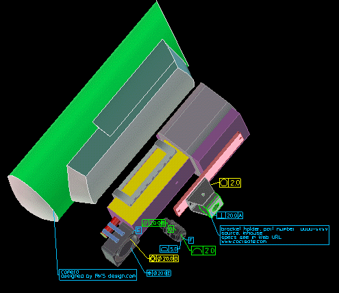
The above example shows a camera assembly with different
parts. Single parts are associated with GD&T symbols. In this tutorial
we will associate a GD&T callout (a GD&T symbol) to a single
part within this assembly.
The Tolerance example for this tutorial:
Let's create a perpendicularity tolerance which consists of one Datum
A and a tolerance callout using the Datum A as the reference.
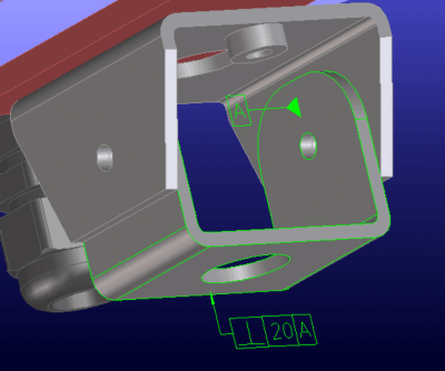
The camera is mounted on two brackets which fit together as
shown in the picture below. The lower mounting bracket is the part which
will have the perpendicularity tolerance attached.
1. Load and activate the GD&T Advisor Module:
Under File > Modules > Additional Functionality click GD&T. This loads the GD&T Advisor module and also activates (without
highlighting the yellow button) the Design Information functionality.
Note: As a prerequisite, the codeword of the GD&T module is available
in the ME-License server file MEls.conf (see the installation directory
of the ME-License server, or contact your system administrator).
2. Load the 3D model
The model can be found under your installation directory ".../documentation/GDT_advisor/gdt_tut/models/camera1.pkg"
Load the package file and position the model as shown in the picture.
Select the bracket part bkt.upper as the active part.
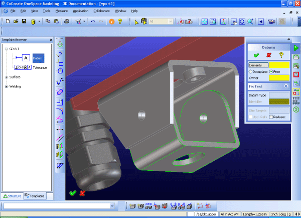
3. Open the GD&T menu to associate GD&T symbols to 3D models
Open the Document3D menu and click GD&T. This offers to create
Datums or Tolerances. A Datum must first exist before a Tolerance Callout
can use it.
4. Create a Datum reference for a Tolerance Callout
Zoom into the model as shown in the picture and position the model
to attach a datum symbol.
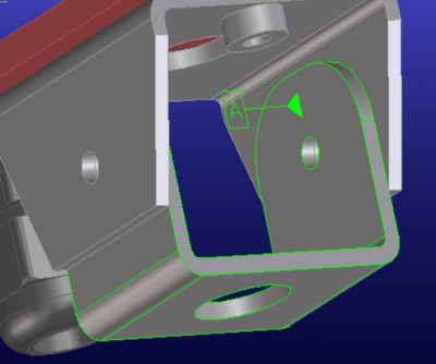
Create a datum by pressing Datums and pick the planar inner face
of the bracket part. It shows you the datum type surface which
is a planar surface. Enter the identifier A and click ok. The datum flag
A is then generated and put on the surface and displayed in perpendicular
direction to the surface.
5. Create the Perpendicularity Tolerance Callout
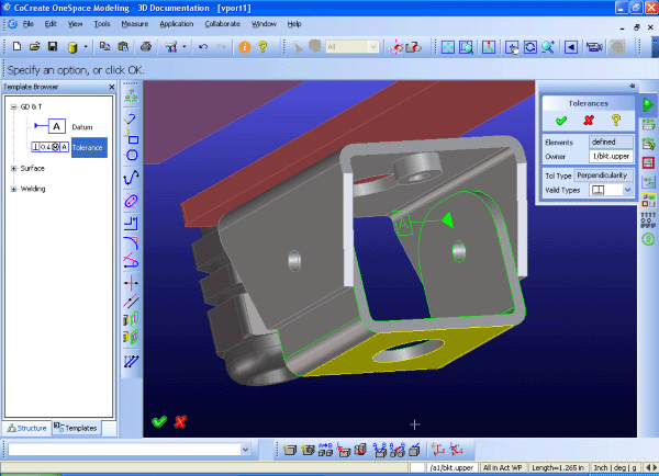
In the GD&T Create menu press Tolerances which offers to pick a face
to attach a tolerance. The intended face should
be perpendicular to the surface referenced by Datum A. Select the lower face of the bracket with the big through hole in the middle.
Press Valid Types and the
system shows which tolerance types are possible to attach. Select and click
the Perpendicularity symbol. Modeling displays it in the menu.
Click OK. Then the Perpendicularity Menu shows up and you can enter
further parameters. The mandatory parameters are indicated in yellow color.
Fill in the required parameters. For example for the Zone Size enter
20. Then click the Datums button which gives you the choice to select a
Datum on the model.
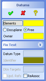
The Datum menu appears amd allows you to enter one or more Datums.
For this perpendicularity Symbol only one Datum is required. Click Primary
and select the Datum A on the 3D model in the viewport. Click OK, then the
Datum reference is defined as shown in the menu. You can attach
optional Fixed Text or pick advanced options if you wish. Click OK and the tolerance callout is shown on the 3D model.
See in the picture below.

Perpendicularity Tolerance with the Datum A and
the Tolerance callout
including the tolerance zone
6. Display and position the tolerance symbols on the 3D model according
to your needs
The Tolerance callout symbols and the Datum references can be repositioned
or oriented according to user requirements. In the Properties menu you
can modify the appearance of the symbols.
Store the work you've done so far. You can elaborate other
tolerance types yourself.


