|
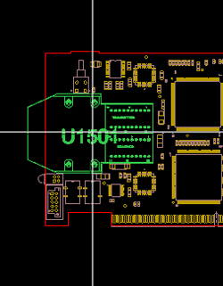
A PCB Layout view shows the placement of objects in a design. The designs are made up of layers, and within each layer are one or more sublayers. The sublayers contain information specific to the design, such as pads, vias, routes, and other geometries associated with the conductive pattern. Sublayers also show information about boards, such as regions and bends. Some of the layers, such as the Global layer, are generated by Creo View, while others are imported from the ECAD tool. You may see a Miscellaneous layer, an Annotations layer, or both, depending on your ECAD data.
|
 |
 Substructure pane when you select any of the following objects: