About Sectioning
|
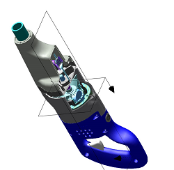
You can create a section view in a figure by cutting the 3D model with one or two planes. Each figure in a C3DI file can have a different section view. Sectioning alters the display of the figure, not the underlying MCAD data or sBOM. You can designate nonsolid parts as solid geometry for sectioning purposes. When you set this option, the section is automatically capped.
Two types of section cuts are available:
• Planar—Made by one plane
• Quarter Cut—Made by two initially perpendicular planes.
|
 |
You can reposition the section planes in the graphics area using the Transform and Free Rotation tools, or you can use the Section Properties dialog box to set the orientation and location numerically, or by reference. The section view changes dynamically to reflect changes in these settings. By default, all parts are sectioned. To section only part of the structure, you can create and modify a list of parts to section.