Settings for Creating, Saving, and Publishing 2D Illustrations
You can change the settings below in the Save Figure As <file type>—Settings dialog box when you save or publish a figure to a 2D illustration file. See the tables below for descriptions of these settings:
• HLR (Hidden Line Removal)
• Rendering lines
• Cropping
• Including a shaded image
• Including a shaded raster image
• Mapping hotspots
• Tolerances
• CGM-specific settings
• SVG-specific settings
• Languages
HLR Settings
Define one or more of the settings described below.
|
Setting
|
Description
|
|
Thick/thin lines
|
Creates thick lines on outer edges and thin lines on inner edges. (See Inner edges below.) Thick lines are rendered in the Thick line pen settings. |
|
Inner edges
|
Creates thin lines on inner edges based on the Thin line tolerance threshold angle and Create surface borders settings in Creo Illustrate Options. The greater the Thin line tolerance threshold angle, the fewer thin lines are created on inner edges. If Thin line tolerance is 0 degrees, or if Create surface borders is selected, thin lines are created on all edges between surfaces. |
|
Surface borders
|
Sets all thin lines on edges between surfaces visible and renders them in the current Thin line pen. |
|
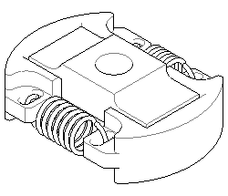
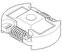
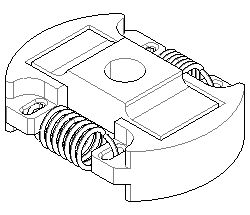
Enhanced intersections
|
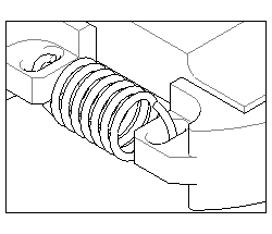
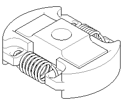
Adds missing lines to intersections between parts. Enabling this setting can substantially increase the processing time for an operation; in many cases you may not need to use it.
Without Enhanced intersections With Enhanced intersections |
Rendering Lines
Select one of these ways to render lines in the illustration.
|
Rendering Type
|
Description
|
|
Bezier paths
|
Converts line segments into Bezier paths.
|
|
Generate ellipses
|
Converts circular line segments into ellipses.
|
Cropping
Crop the illustration or zoom to fit the entire figure.
|
Selection
|
Description
|
|
Select Crop to window
|
• Matches the figure zoom level. • Includes only visible objects that are inside the figure window. • Crops visible objects that are on figure window boundaries. • Shows the figure window boundaries using four line elements. |
|
Clear Crop to window
|
• Includes all visible objects in the figure, even if they are wholly or partially outside the figure window. • Zooms to fit all visible objects in the figure. |
SVG-specific Options
The following options apply to creating SVG files.
|
Selection
|
Description
|
|
Scalable
|
To create a graphic with relative size attributes.
|
|
Fixed size
|
To create a graphic with absolute size attributes.
|
Hotspots
|
Setting
|
Description
|
|
Include symbol hotspot information
|
For illustrations with hotspots, exports an image map (*.imap) file showing the coordinate locations of hotspots in the figure. The map file is saved with the illustration file.
|
|
Include hotspots for callouts
|
Although adding the hotspots can simplify the JavaScript for creating an interactive application, they also increase the file size. Clear this check box to turn off the creation of hotspots for callouts.
|
|
Combine hotspots for same item
|
Groups hotspots by item.
|
|
Export all hotspots individually
|
Creates individual hotspots. Select this option to highlight a particular occurrence of a hotspot, such as in a procedure manual.
|
Tolerances
Set the tolerances for lines in a 2D figure (for 2D figure creation only).
|
Selection
|
Description
|
|
Thin line tolerance
|
Sets the threshold angle between three facets that share an edge. The greater the Thin line tolerance, the fewer thin lines are created.
|
|
Gap tolerance
|
Increasing the gap tolerance will result in fewer gaps in lines that should be a single unbroken line.
Decreasing the gap tolerance number will result in fewer ‘unwanted’ lines seen in curved surfaces.
|
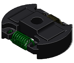
Including a Shaded Image
Add a shaded image of the figure.
|
Selection
|
Description
|
|
Select Include shaded image
|
Includes a shaded image of the figure in the 2D illustration file. | The render mode set in the 3D figure controls the type of shaded image included. A separate raster image is created for each inset in the 2D figure when the option in set to On. |
|
|
Resolution
|
Enter a resolution value for the shaded image from 50 to 600 pixels per inch. You can also set a default resolution in the Creo Illustrate Options dialog box, as described above.
|
CGM-specific Options
The following options apply to creating CGM files.
|
Option
|
Description
|
|
Profile
|
Specifies which CGM intelligent graphics encoding model is used to create the 2D CGM illustration file. The models are described in the next rows.
|
|
ISO 8632 : 1999
|
International Standards Organization open standard defined in ISO/IEC 8632:1999, 2nd Edition.
|
|
WebCGM 2.0 and 2.1
|
CGM profiles developed by the CGM Open consortium and approved by the World Wide Web Consortium (WC3) for use on the Web.
|
|
ATA GREXCHANGE Versions 2.4, 2.5, 2.6, 2.7, 2.8, 2.9, and 2.10
|
CGM profiles published by the Air Transport Association's Graphics Working Group.
|
Languages
Set the language options.
|
Setting
|
Description
|
|
Select Publish all languages
|
Publishes one file for each figure in all target languages.
|
|
Clear Publish all languages
|
Publishes one file in the source language only.
|