Setting Fiber End Details
Fiber end geometry defines the routes used to connect multiple fibers to a single port. Three dimensions facilitate the use of minimal-length fiber, as shown in the figure below.
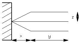
In addition, you can define the number of pairs of non-straight end geometries or fans and the maximum number of connections per port. The total number of separate routes into a port is 1+2*<number of fans>.
The first fiber connected uses the middle geometry which is straight. Subsequent fibers use remaining routes. If there are more connections than available routes, the middle geometry is used.
Fiber end geometry can be specified for a diagram type or individual ports.
1. In the Port Properties dialog box, click Fiber End Details.
2. In the Port Properties: Fiber End Details dialog box, choose Wiring from the Diagram type drop down list.
3. Edit the Max connections per port to 4, and click OK.
4. In the Port Properties dialog box, click OK.