|
Step
|
Example
|
Result
|
|
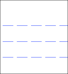
Place 3 conductor construction lines
|
 |
|
|
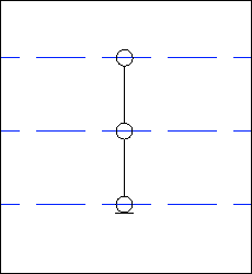
Draw geometry representing the coaxial part of the decoration:
• Circles on the conductors
• Straight lines connecting the circles
• A straight horizontal line below the bottom conductor
|
 |
|
|
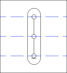
Draw geometry representing the overbraid part of the decoration:
• A slot covering all conductors
|
 |
|
Select the slot and click  Set Overall. Set Overall. |
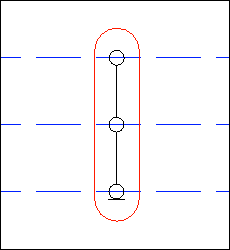 |
The slot or overbraid geometry expands to be over all conductors.
|
Click  Set Fixed and select the circles and lower line. Set Fixed and select the circles and lower line. |
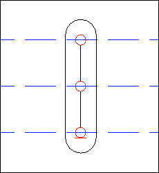 |
The top circle remains fixed to the top conductor of the cable. The bottom circle remains fixed to the bottom conductor of the cable. The middle fixed part applies to all intermediate conductors when the number of conductors is > 2
|
|
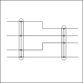
Clear the View Fixed and View Overall check boxes. Only the straight vertical lines remain. Select the lines and click  Set Scalable. Set Scalable. |
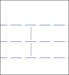 |
The selected geometry is scaled to maintain the distance between the ends of a part and the nearest conductor.
|