Defining the Variable Connector Shape
1. Select
Variable Connector and click

to create a new shape.
2. Click

to open the shape.
3. Close the Catalog Explorer.
4. In the Graphics Toolbar, click

.
5. In the Grids: Current Sheet dialog box, select Ports and click Switch.
6. From the Display group, make sure the Display grid on screen check box is selected.
7. Click OK.
8. In the ribbon, click Geometry.
9. Click
 Box – Opposite Corners
.
10. In the graphics area, click to select a start point.
11. In the bottom right corner below the graphics area, edit the Width to 3 and the Height to 6.
12. Click

and press ESC to exit the draw box tool.
13. Click
and then click
Add.
14. In the Add Grid dialog box edit the name to half.
15. Edit the to spacing 0.75 and click OK.
16. In the Grids: Current Sheet dialog box, select the newly created grid, click Switch, and then click OK.
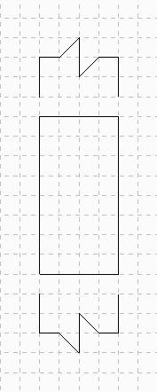
17. From the
Line group, click
 Thin Solid line
 and draw the two lines as shown in the figure.