Creating Geometry
1. In the ribbon, click Geometry.
2. From the
Line group, click
 Box – Opposite Corners
.
3. In the graphics area, click to select a start point.
4. In the bottom right below the graphics area, edit the Width to 18 and edit the Height to 12.
5. Click

.
6. Press ESC to exit the draw box tool.
7. From the
Edit Line group, click the arrow next to
Point and choose
 Line navigation
.
8. In the graphics window, double-click on the bottom left corner of the rectangle. The line enters edit mode.
9. From the edit line group, click
 Fillet
.
10. In the bottom right below the graphics areas, edit the
Radius to
3 and click

.
11. In the
Line Navigation dialog click

.
12. From the edit line group, click
Fillet.
13. Edit the
Radius to
3 and click
.
14. Repeat the fillet steps for the remaining two corners.
15. Right-click and choose Exit Tool to exit the edit line command.
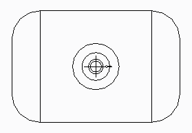
16. In the ribbon, explore the line tools in the Geometry tab to finish the graphics as per the figure.
17. In the ribbon, click Catalog.
18. From the
Info group, click
 Set Datum
.
19. Place the origin of the port to be in the centre of the circle.