To Define Groove or Butt Weld Options
You must be on the Groove Weld or Butt Weld tab to perform this procedure.
1. Click the Options tab.
2. To set the weld geometry representation, under Weld geometry type, select Surface, Light, or Solid.
3. To set a method for calculating the weld cross section when surface or light geometry represents the weld, under Weld cross section, select an option:
◦ By Reference. Select a plane.
◦ By Value. Type a value.
4. Select a predefined welding material from the Weld material list, or click Define to open the Weld Materials dialog box and define a new welding material.
5. Select a predefined welding process from the Weld process list, or click Define to open the Weld Processes dialog box and define a new welding process.
6. To define the visibility of the all-around weld symbol, select an option from the
 All-around weld
 list:
◦ No—Do not show the all-around weld symbol in the weld feature symbol, even when the feature detects a closed weld trajectory.
◦ Yes—Show the all-around weld symbol in the weld feature symbol, even when the feature detects an open weld trajectory.
◦ Automatic—Show the all-around weld symbol in the weld feature symbol only when the feature detects that all the weld trajectories are closed.
7. To define the weld as a field weld, select the
 Field weld
 check box.
8. To define a weld finish, choose one of the following options:
◦ ANSI: Select an option from the Finish list: None, Chipping, Grinding, Hammering, Machining, Rolling, or Unspecified.
◦ ISO: Select the
 Finish
 check box to set the finish to ISO standards.
9. Select an option from the
Contour list:
None,
 Flat
Flat,
 Convex
,
 Concave
, or
 Smooth Blend
 (smooth blend for ISO only).
10. In the Back type list, select one of the following options:
◦ None
◦ Backing, and then select the type of strip to use from the Backing list.
▪ To use a permanent strip, select
 Keep
Keep (ANSI) or
 Permanent strip
 (ISO).
▪ To use a removable strip, select
 Remove
 (ANSI) or
 Removable strip
 (ISO).
◦ Back weld, and then do the following actions:
1. Select the Back size check box, and then set a value for the back weld size.
2. Define a back finish according to the used welding standard:
▪ ANSI: Select an option from the Back finish list: None, Chipping, Grinding, Hammering, Machining, Rolling, or Unspecified.
▪ ISO: Select the
Back finish check box to set the back finish to ISO standard.
3. Select an option in the
Back contour list:
None,
Flat,
Convex,
Concave, or
Smooth blend (smooth blend for ISO only).
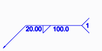
11. To show the sequence ID number in the welding symbol tail, select the Display sequence ID check box. To hide the sequence ID number, clear the check box.
Show sequence ID | Hide sequence ID |
| |
12. To keep the weld ID number the same regardless of subsequent actions, select the Keep ID in sequence check box.