Working with Finish and Rest Finish Parameters
Watch the
video that shows you how to work with Finish and Rest Finish parameters. This tutorial is a step-by-step guide on how to create HSM Finish and Rest Finish sequences.
Working with Finish Options
1. Open the MFG0001.ASM assembly.
2. On the Model Tree, click
Mill window 1 and then click

to edit the definition. The
Mill Window tab opens.
3. On the Options tab, select On window contour and click OK.
4. On the Model Tree, click the sequence
FINISH_SMART_CUTS and then click
to edit the definition. The
HSM Finish tab opens.
5. Click

and select
KF20_ISO50 tool with a cutter diameter of 20 mm.
6. On the References tab, click the Mill window collector and on the Model Tree, select Mill Window 1.
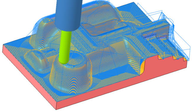
7. On the Parameters tab, the parameters are populated automatically, based on the tool diameter. To optimize the toolpath, set values as shown for the following parameters:
◦ STEP_OVER = 0.5
◦ FINISH_OPTION = SMART_CUTS
◦ CUT_TYPE = CLIMB
8. Click the arrow next to

and then click

. The
Material Removal tab opens.
9. On the Material Removal tab, click Stock Model > Open In-Process Stock. The Load stock dialog box opens.
10. Select rest_rough.bin and click Open.
11. Click
to open the
Play Simulation dialog box.
12. Click

to play simulation.
13. On the
Material Removal tab, click

.
14. On the Parameters tab, set values as shown for the following parameters and then repeat steps 8–13:
◦ STEP_OVER = 1
◦ SLOPE_ANGLE_START = 0
◦ SLOPE_ANGLE_END = 40
|  Slope angle that starts from 0 indicates that only shallow areas are machined. |
15. On the Parameters tab, set values as shown for the following parameters and then repeat steps 8–13:
◦ STEP_OVER = 1
◦ SLOPE_ANGLE_START = 38
◦ SLOPE_ANGLE_END = 90
| Slope angle that ends in 90 indicates that only steep areas are machined. |
16. Click OK on the HSM Finish tab to complete the sequence.
17. On the Model Tree, click the sequence
FINISH_CONSTANT_Z and then click
to edit the definition. The
HSM Finish tab opens.
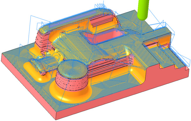
18. On the Parameters tab, set values as shown for the following parameters and then repeat steps 8–13:
◦ STEP_OVER = 5
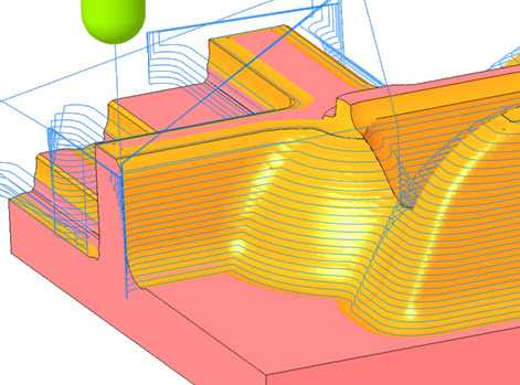
◦ FINISH_OPTION = CONSTANT_Z
◦ CUT_TYPE = CLIMB
◦ LEAD_RADIUS = 15
◦ CUT_ENTRY_EXIT_EXT = HORIZONTAL_TANG_ARC
19. On the Parameters tab, set values as shown for the following parameter and then repeat steps 8–13:
◦ STEEP_STEP_OVER = 2
| When you set the STEEP_STEP_OVER parameter the STEP_OVER value is ignored for the steep areas. |
20. Click OK on the HSM Finish tab to complete the sequence.
21. On the Model Tree, click the sequence
FINISH_PARALLEL_CUT and then click
to edit the definition. The
HSM Finish tab opens.
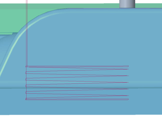
22. On the Parameters tab, set values as shown for the following parameters and then repeat steps 8–13:
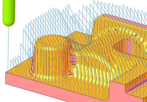
◦ STEP_OVER = 5
◦ FINISH_OPTION = PARALLEL_CUT
◦ CUT_TYPE = CLIMB
◦ CUT_ANGLE = 45
◦ LEAD_RADIUS = 15
◦ CUT_ENTRY_EXIT_EXT = VERTICAL_TANG_ARC
23. On the Parameters tab, set values as shown for the following parameters and then repeat steps 8–13:
◦ CUT_TYPE = ZIG-ZAG
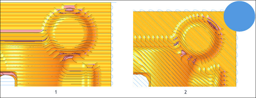
◦ OPTIMAL_ANGLE = YES
1. OPTIMAL_ANGLE is set to YES.
2. OPTIMAL_ANGLE is set to NO.
24. Click OK on the HSM Finish tab to complete the sequence.
25. On the Model Tree, click the sequence
FINISH_CONSTANT_CUSP and then click
to edit the definition. The
HSM Finish tab opens.
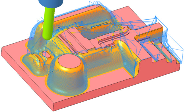
26. On the Parameters tab, set values as shown for the following parameters and then repeat steps 8–13:
◦ STEP_OVER = 5
◦ CUT_TYPE = CLIMB
◦ FINISH_OPTION = CONSTANT_CUSP
◦ SPIRAL_SCAN_DIRECTION = INSIDE_OUT
27. On the Parameters tab, set values as shown for the following parameters and then repeat steps 8–13:
◦ SPIRAL_SCAN_DIRECTION = OUTSIDE_IN
◦ SCALLOP_HGT = 0.01
| The lesser value of SCALLOP_HGT parameter results in smoother finishing. |
28. On the Parameters tab, set values as shown for the following parameters and then repeat steps 8–13:
◦ SLOPE_ANGLE_START = 0.1
◦ SLOPE_ANGLE_END = 45
| The slope angle of more than 0 indicates that the flatlands are excluded from the path calculation. |
29. Click OK on the HSM Finish tab to complete the sequence.
30. On the Model Tree, click the sequence
FINISH_FLAT_LANDS and then click
to edit the definition. The
HSM Finish tab opens.
31. Click
and select
HOLDER_END_MILL tool with a cutter diameter of 20 mm.
32. On the Parameters tab, set values as shown for the following parameters and then repeat steps 8–13:
◦ STEP_OVER = 6
◦ FINISH_OPTION = FLAT_LANDS
◦ SCALLOP_HGT = 0.01
Working with Finish Cut Type Options
1. On the Model Tree, click the sequence
FINISH_CUT_TYPE and then click
to edit the definition. The
HSM Finish tab opens.
2. Click
and select
HOLDER_END_MILL tool with cutter diameter of 12 mm.
3. On the References tab, click the Mill window collector and on the Model Tree, select Mill Window 2.
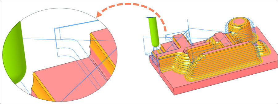
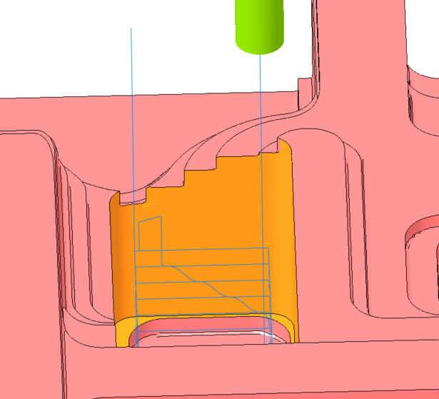
4. On the Parameters tab, the parameters are populated automatically, based on the tool diameter. To optimize the toolpath, set values as shown for the following parameters:
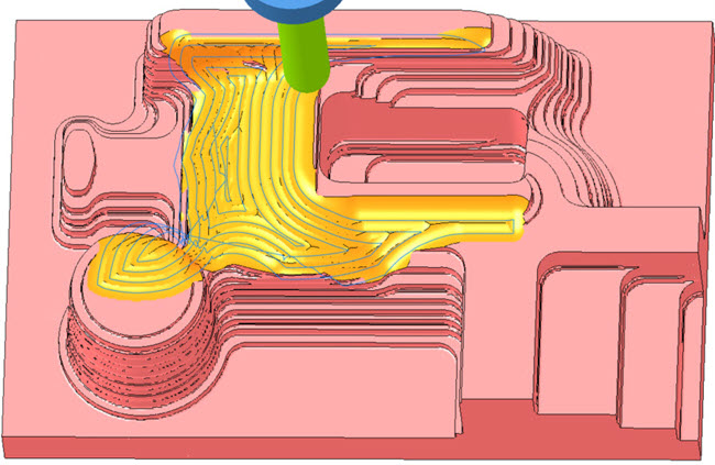
◦ STEP_OVER = 5
◦ FINISH_OPTION = CONSTANT_Z
◦ CUT_TYPE = CLIMB
◦ START_HEIGHT = 40
◦ END_HEIGHT = 10
5. Click the arrow next to
and then click
. The
Material Removal tab opens.
6. On the Material Removal tab, click Stock Model > Open In-Process Stock. The Load stock dialog box opens.
7. Select rest_rough.bin and click Open.
8. Click
to open the
Play Simulation dialog box.
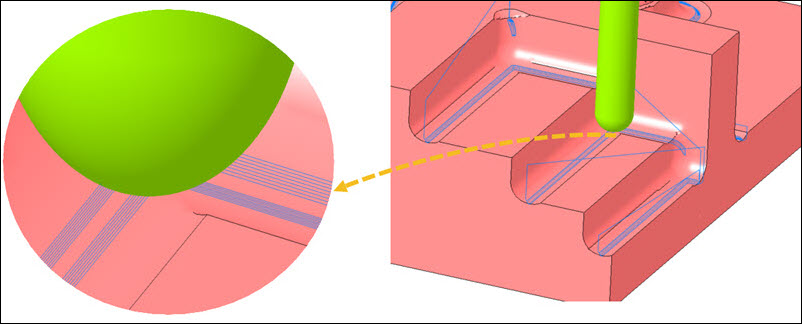
9. Click
to play simulation.
| The S type connection is observed when CUT_TYPE is set to CLIMB. |
10. Click Close on the Material Removal tab.
11. On the Parameters tab, set values as shown for the following parameters and then repeat steps 5–10:
◦ STEEP_STEP_OVER = -
◦ CUT_TYPE = SPIRAL
12. On the Parameters tab, set values as shown for the following parameter and then repeat steps 5–10:
◦ CUT_TYPE = UPCUT
| The S type connection is observed when CUT_TYPE is set to UPCUT. |
Working with Rest Finish Options
1. On the Model Tree, click the sequence
REST_FINISH_PENCIL and then click
to edit the definition. The
HSM Rest Finish tab opens.
2. Click
and select
KF12_ISO50 tool with a cutter diameter of 12 mm.
3. On the References tab, click the Mill window collector and on the Model Tree, select Mill Window 1.
4. On the Parameters tab, the parameters are populated automatically, based on the tool diameter. To optimize the toolpath, set values as shown for the following parameters:
◦ STEP_OVER = 1
◦ FINISH_OPTION = PENCIL_CUT
5. Click OK to complete the sequence REST_FINISH_PENCIL.
6. Press CTRL and then click the sequences FINISH_SMART_CUTS and REST_FINISH_PENCIL.
7. Click
to open
Material Removal tab.
8. On the Material Removal tab, click Stock Model > Open In-Process Stock. The Load stock dialog box opens.
9. Select rest_rough.bin and click Open.
10. Click
to open the
Play Simulation dialog box.
11. Click
to play simulation.
12. Click Close on the Material Removal tab.
13. On the Model Tree, click the sequence
REST_FINISH_PENCIL and then click
to edit the definition. The
HSM Rest Finish tab opens.
14. On the Parameters tab, set values as shown for the following parameters:
◦ STEP_OVER = 0.1
◦ MULTI_PENCIL_PASSES = 10
15. Click OK to complete the sequence REST_FINISH_PENCIL and repeat steps 6–12.
16. On the Model Tree, click the sequence
REST_FINISH_CONSTANT_CUSP and then click
to edit the definition. The
HSM Rest Finish tab opens.
17. Click
and select
KF12_ISO50 tool with a cutter diameter of 12 mm.
18. On the References tab, click the Reference Cutting Tool collector and select the tool KF20_ISO50 .
19. On the References tab, click the Mill window collector and on the Model Tree, select Mill Window 1.
20. On the Parameters tab, the parameters are populated automatically, based on the tool diameter. To optimize the toolpath, set values as shown for the following parameters:
◦ STEP_OVER = 0.5
◦ CUT_TYPE = CLIMB
◦ FINISH_OPTION = CONSTANT_CUSP
21. Click OK to complete the sequence REST_FINISH_CONSTANT_CUSP.
22. Press CTRL and then click the sequences FINISH_SMART_CUTS and REST_FINISH_CONSTANT_CUSP.
23. Click
to open
Material Removal tab.
24. On the Material Removal tab, click Stock Model > Open In-Process Stock. The Load stock dialog box opens.
25. Select rest_rough.bin and click Open.
26. Click
to open the
Play Simulation dialog box.
27. Click
to play simulation.
28. Click Close on the Material Removal tab.
29. On the Model Tree, click the sequence
REST_FINISH_CONSTANT_CUSP and then click
to edit the definition. The
HSM Rest Finish tab opens.
30. On the Parameters tab, set values as shown for the following parameter:
◦ REST_AREA_OFFSET = 5
31. Click OK to complete the sequence REST_FINISH_CONSTANT_CUSP and repeat steps 21–28.