Cyclone Separator Exercise 1—Extracting the Fluid Domain
Fluid domain extraction is the creation of a closed geometric region that surrounds the fluid.
1. Click Home > Select Working Directory and navigate to the FlowAnalysisModels folder. Click OK.
2. Click
File >
 Open
Open.
3. From the File Open dialog box, browse to the cyclone_assembly folder and select cyclone_4.asm. Click Open.
4. Click

in the Graphics toolbar to display the style elements. Select
Shading, or
 Shading with Edges
.
5. Click the Applications tab.
6. Click
 Flow Analysis
. The
Flow Analysis tab opens.
7. Click
 New Project
. If the Residual plot opens, close it.
8. Click
 Create Fluid Domain
. The
Fluid Domain Creation tab opens.
9. Click the Openings tab.
10. Click the Faces box. The Surface Sets dialog box opens.
11. In the Surface Sets dialog box, under Included surfaces right-click all the surfaces and click Remove All.
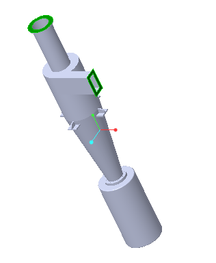
12. In the graphics window, press CTRL and select the two surfaces shown below. Two surfaces appear in the Surface Sets dialog box, under Included surfaces.
13. Click OK.
Adding the Simulation Domain
1. In the Fluid Domain Creation tab select Add to Simulation.
2. Click

to create the fluid domain.
CYCLONE_4_1_FLUID.prt appears in the Model Tree and
CYCLONE_4_1_FLUID is added under
Domains.
3. The boundaries for the Boundary ConditionsBC_1 and BC_2 and CYCLONE_4_1_FLUID are created automatically and appear in the Flow Analysis Tree under Boundary Conditions > General Boundaries.