Example 3: Topology Design with Displacement Constraints
Use the model controlarm.prt for this example.
Description
This example demonstrates a topology optimization with a mass fraction objective, and displacement constraints.
Highlighted features
Minimize Mass Fraction, Displacement constraints, Fill symmetrically fabrication constraint, Power Rule
Optimization problem statement
The following optimization problem will be created and solved:
• Objective:
◦ Minimize Mass Fraction
• Subject to:
◦ Displacement in analysis 1 ≤ 10.667 mm
◦ Displacement in analysis 2 ≤ 1.17857 mm
Analysis
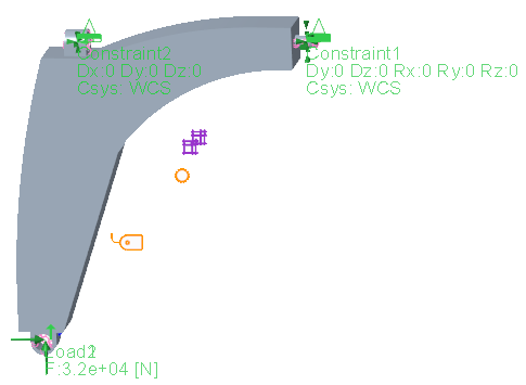
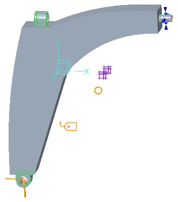
The example contains two analyses. In analysis 1, the force is along the positive X direction. In Analysis 2, the force is along the positive Y direction. The loads/constraints for each analysis are shown in the image below:
Mesh control
Maximum element size: 2 mm
Topology region
• References:
The control arm component, excluding volume region 1, 2, and 3, as shown in the image below
• Init. mass fraction: 1.0
When minimize mass fraction is used as an objective, and displacement as constraints, it is recommended to set the initial mass fraction as 1.0 or a fraction value that does not cause too much violation of the displacement constraints.
• Fabrication constraints:
◦ Filling symmetrically along the Z axis with respect to coordinate system CS0 (F0Z)
◦ Minimum member size: 4 mm
◦ Spread fraction: 0.5
• Power rule:
Rv1=6
For the case of using mass fraction as an objective, Rv1=6 will help get a more polarized answer. Alternatively, you can add Min. Strain Energy as an additional objective to help polarize the topology answer.
Design objective
Minimize Mass Fraction
Design constraints
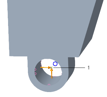
The displacement constraints are defined on the point as shown in the image below.
• Constraint 1
◦ Component: Translation Magnitude
◦ Applied to Analysis 1
◦ Upper bound 10.667 mm
• Constraint 2
◦ Component: Translation Magnitude
◦ Applied to Analysis 2
◦ Upper bound 1.17857 mm
1. Point where displacement constraints are applied
Optimization study
The study refers to the defined topology region, design objectives, and constraints
Advanced settings:
• Max. design cycles = 50
• For analysis output files, only the first and last cycle are requested.
• Use default settings for all other analysis and design parameters.
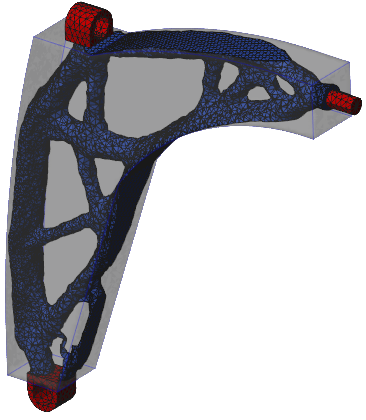
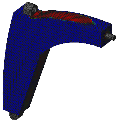
Topology Result
• Topology density isosurface
• Topology element density
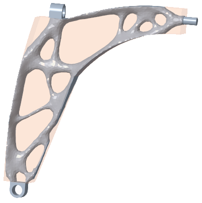
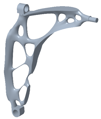
Geometry Reconstruction
• Tessellated model
• Solid model