Example: Using Cyclic Symmetry
Cyclic symmetry relies on the principle that, in a given model, a segment of the geometry can be repeated in a cyclic manner an integer number of times to form the whole of the model. In this case, the segment is not a geometric mirror image. With cyclic symmetry, loading conditions also repeat cyclically. As with mirror symmetry, you work with a segment of the model, but still get an accurate idea of your model's behavior as a whole.
Cyclic symmetry is particularly useful for models where the symmetric segment has a complex shape or the cuts you must make to isolate the symmetric segment are not fully planar. For example, the cuts you would make to isolate one blade of a turbine are likely to bend in one or more directions.
To use cyclic symmetry, you must be able to divide your model in such a way that the segment you chose to work with is repeated cyclically throughout the model. The easiest way to determine whether a model shows this type of symmetry is to imagine cutting the model into identical wedges. If you can slice the model in such a way that the segments are geometrically identical and have loads, constraints, and material properties with cyclically repeatable orientation and placement, your model demonstrates cyclic symmetry. Additionally, for loads applied to specific geometry such as total force loads, the load seen by each segment must have the same value.
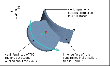
If you want to take advantage of cyclic symmetry in your model, you need to complete two steps—cutting the model into a cyclically repeated segment and applying a cyclic symmetry constraint to the cut surfaces or, in the case of a shell model, to the cut curves. For example, let us say you are working with a fan that has a hole at its center. A shaft secures the fan at the hole, locking it in place in the Z direction but allowing free movement in the T and R directions. The fan bears a centrifugal load with an angular velocity of 700 radians per second about the Z axis. The model qualifies for cyclic symmetry because the geometry, loads, and constraints are all repeated symmetrically.
Looking at the model as a whole, you would first plan the cut lines using a cylindrical coordinate system as a reference. The best choice is as follows:
The segment defined by the cuts repeats four times to form the circumference of the fan. After you cut the model, you need to add a cyclic symmetry constraint to the model so that the solver will correctly interpret the geometry as a cyclic symmetry segment:
Here, you add a cyclic symmetry constraint to both of the cut surfaces. Note that you do not need to change the value of the load to reflect the fact that the load acts on a smaller segment. This is primarily a function of the load type. For example, this model uses a centrifugal load—a body load that, in this case, behaves cyclically. Therefore, the load requires no adjustment. However, if you were working with a total load against the outer surface of the hole, you would need to adjust the load just as you would for
standard symmetry.
Note that this model does not qualify for mirror symmetry because the fan blades are set at an angle, which would preclude mirroring. Additionally, the centrifugal load would not mirror correctly as, in the mirror image, the direction of the load would oppose the actual direction of the load.


