Possible Sheet Metal Design Approach
Consider the following design approach when creating your sheet metal design:
1. Create the basic sheet metal parts in sheetmetal mode. Since many of the components will be held in place with screws or bent tabs, you might want to leave the creation of these features for later when the components are assembled.
2. Assemble all the major internal components relative to each other. Include simple supporting structures, or sheet metal parts that are not completely defined at this time, to place the components. Less important components can also wait.
|
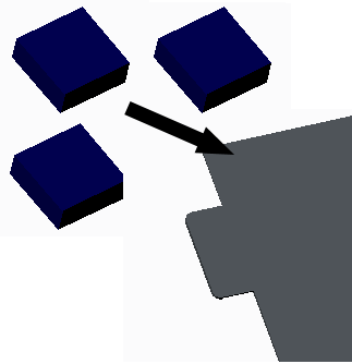
Components and Sheet Metal Platform, Before Assembly
|
|
|
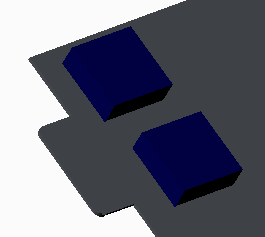
Components and Sheet Metal Platform, After Assembly
|
|
3. Create or modify the sheet metal parts using the internal components as references, if required. Those references aid you in adding any support walls, form features for stiffening panels, and notches or punches for fastening the components.
4. After the cabinet and supporting structures are defined add any remaining sheet metal or assembly features.
|
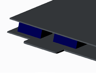
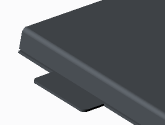
Components and Sheet Metal Enclosure, After Assembly
|
|
|
|
|
5. Create and/or select a bend table to provide material allowances when unbending the part. You could also do this before the first step in the design.
6. In sheet metal mode, create a bend order table to define the bending sequences for each part.
7. Add a Flat State instance. This creates your flat pattern for drawing and manufacturing. The bend table data ensures that the flat pattern’s geometry is accurate.
8. Creating drawings to document your parts. You can include both the generic (as designed) part and the Flat State instance (multi-model drawing). Show the dimensions each model. Then add the bend order table as a note.