
 ).
). |  |
). |  |
)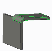 |  |
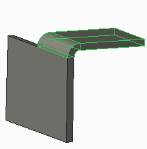
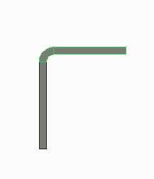
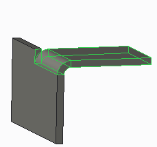
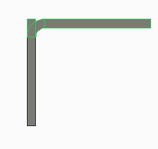
Non-coplanar Surfaces | Coplanar Surfaces |
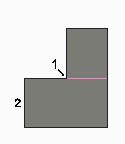  |   |
BLA = L - ( R + T ) | |
Where: BLA = Bend line adjustment L = Developed length of the bend (determined from a bend table or formula) R = Inside radius of the bend T = Thickness of the sheet metal RL = Relief length ( = cutback length in rip relief) | |
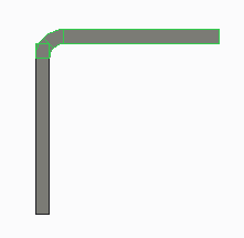
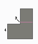
, bend material on both sides of bend line, command. When you use other options, the bend line coincides with either of the tangent edges between the bend area and the adjacent planar area. An axis is created for the manufacturing bend line in the Unbend and Flat Pattern tools.