Example: Remove Pipe Segment
Use the sample assembly provided at <Creo load point>\Common Files\help\sample_models\piping\piping_assembly_gaps when working in this exercise. It is recommended that you create a copy of the piping_assembly_gaps folder on your computer before you start working with this exercise.
Remove the Pipe Segment
1. Set the piping_assembly_gaps folder as the Working Directory.
2. Open pipe_gaps.asm.
3. Click
Applications >
 Piping
. The
Piping tab opens.
4. Click
 Route Pipe
 and select the pipe segment to route. A warning message opens.
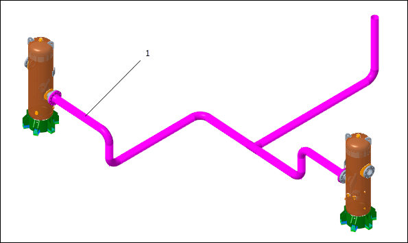
1. Pipe segment
5. Click Confirm in the warning message.
6. Click
 Edit Segment
 >
 Remove Pipe Segment
. The
Pipe Remove Segment tab opens.
7. Select the same pipe segment that you had selected earlier.
8. Select the Elbow fitting connected to the selected pipe segment.
1. Elbow fitting
9. Press and hold SHIFT and select the Elbow fitting to move.
1. Elbow fitting
10. Click

. The pipe segment is removed.
Reduce the Pipe Segment Length
1. Click
Edit Segment >
Remove Pipe Segment. The
Pipe Remove Segment tab opens.
2. Select the pipe segment to edit.
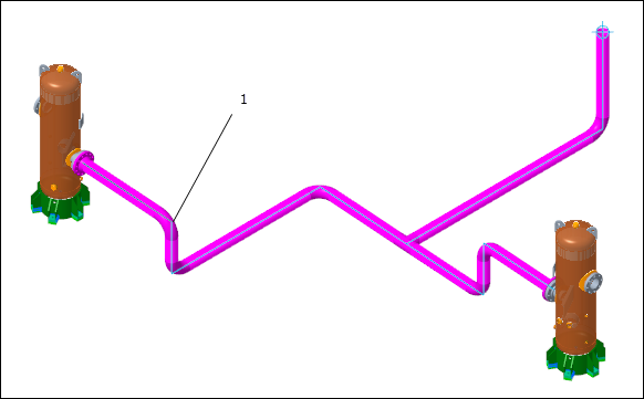
1. Pipe segment
3. Click the References tab and click Details. The Segment Collection dialog box opens.
4. Select the Elbow fitting to move in the graphics area.
1. Elbow fitting
5. Click in the Bounds box and select the Elbow fitting in the graphics area.
1. Elbow fitting
6. Click OK. The Segment Collection dialog box closes.
7. Click

to edit the pipe segment length.
8. Do one of the following:
◦ Specify the length of the remaining pipe segment in the text box and press TAB.
◦ Drag the fitting in the graphics window to reduce the pipe segment.
1. Fitting
9. Click
. The length of the selected pipe segment is reduced.
Reduce the Pipe Segment with Automatic Connect at Break Points
1. Click
 Break Point
. The
Break Point dialog box opens.
2. Select the pipe segment to add a break point.
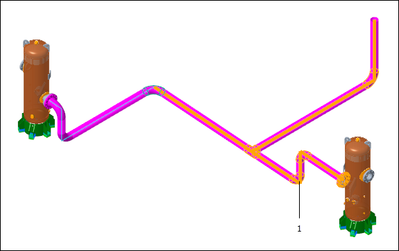
1. Pipe segment
3. Click Apply. A break point is created.
4. Click another pipe segment to add a break point.
1. Pipe segment
5. Click OK. The second break point is created.
6. Click
Edit Segment >
Remove Pipe Segment. The
Pipe Remove Segment tab opens.
7. Select the pipe segment to edit.
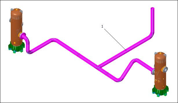
1. Pipe segment
8. Select the fitting to move.
1. Fitting
9. Click the References tab and click Details. The Segment Collection dialog box opens.
10. Click in the Bounds box. Press and hold CTRL and select the two pipe segments as a collection boundary.
1. Pipe segments
11. To include the segments as the boundary, do one of the following:
◦ Select Included in the Include/Exclude box.
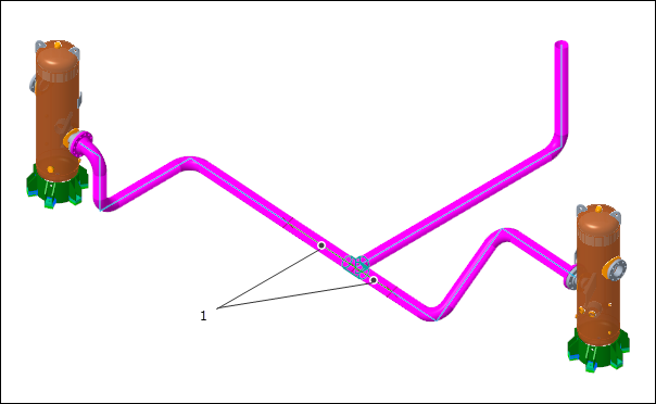
◦ Click the dots in the graphics window.
1. Dots
12. Click OK. The Segment Collection dialog box closes.
13. Click the Options tab and select the Enable automatic connect check box.
14. Click
to edit the pipe segment length.
15. Drag the fitting in the graphics window to reduce the pipe segment.
1. Fitting
16. Click
. The length of the selected pipe segment reduces with automatic connect at the break points.
17. Click
Route Pipe to stop routing pipes.
Delete the Edit Segment Features
1. Click

and clear the
Pipeline View check box.
2. On the Model Tree, expand STEAM-1.ASM.
3. Right-click
Pipe Remove Segment id 133 and click
 Delete
. Click
OK. The selected feature is deleted.
4. Right-click
Pipe Remove Segment id 148 and click
Delete. Click
OK. The selected feature and its components are deleted.
5. Right-click
Pipe Remove Segment id 131 and click
Delete. Click
OK. The selected feature is deleted.